Lenze · i700 servo inverter · reference manual · DMS 3.0 EN · 06/2016 · TD06 184
7 CiA402 device profile
7.4 Device control
_ _ _ _ _ _ _ _ _ _ _ _ _ _ _ _ _ _ _ _ _ _ _ _ _ _ _ _ _ _ _ _ _ _ _ _ _ _ _ _ _ _ _ _ _ _ _ _ _ _ _ _ _ _ _ _ _ _ _ _ _ _ _ _
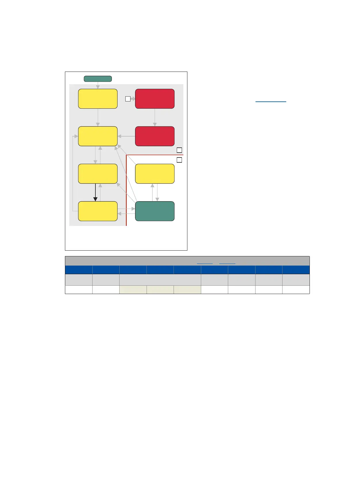
7.4.1.2 Switching on
From all states
Power section inhibited (pulse inhibit)
Power section enabled
This command serves to deactivate the switch
on inhibit which is active after switch on or
after the reset (acknowledgement) of an error.
• A changeover to the "Switched on
" device
status takes place.
Bit pattern for the "Switch on" command in the Controlword (0x6040 or 0x6840 for axis B):
Bits 15 - 8 Bit 7 Bit 6 Bit 5 Bit 4 Bit 3 Bit 2 Bit 1 Bit 0
Fault reset Control bits depending on the operating mode Enable
operation
Activate quick
stop
Enable voltage Switching on
X0X X XX111
1
2
0
Ready to
switch on
Not ready to
switch on
Switched
on
Operation
enabled
Fault reaction
active
Fault
Switch-on
disabled
Quick stop
active
Power-on

 Loading...


