5 Motor control & motor settings
5.12 Fine adjustment des motor model
135
Lenze · i700 servo inverter · reference manual · DMS 3.0 EN · 06/2016 · TD06
_ _ _ _ _ _ _ _ _ _ _ _ _ _ _ _ _ _ _ _ _ _ _ _ _ _ _ _ _ _ _ _ _ _ _ _ _ _ _ _ _ _ _ _ _ _ _ _ _ _ _ _ _ _ _ _ _ _ _ _ _ _ _ _
5.12.1.1 Example for determining the saturation characteristic
Given values:
• Rated motor current: 5 A
• Maximum motor current: 20 A
• Maximum process current: 15 A
Procedure:
1. Deactivate correction: Set all subindices of object 0x2C04
(or 0x3404 for axis B) to 100 %.
2. Use object 0x2C05
(or 0x3405 for axis B) to set the maximum current up to which the motor is
to be actuated in the process (in this example "15 A").
3. Adjust the current controller with different current setpoints by means of the manual test mode
"current pulse" and take down the corresponding settings for Vp and Tn.
• The procedure is described in the Manual test mode "Current pulse"
chapter. ( 107)
• The current setpoints to be set for the corresponding adjustment in object 0x2835:1
(or
0x3035:1
for axis B) result from the scaling of the maximum process current to the X axis of
the saturation characteristic.
• The grid points which are required to define the saturation characteristic with a sufficient
quality varies from motor to motor and thus has to be determined individually.
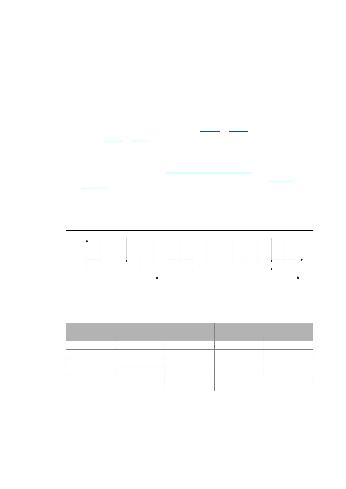
• For this example, currents that are part of the grid points 5, 9, 13, and 15 have been selected,
and a measurement at rated motor current was carried out additionally:
[5-5] Saturation characteristic: Distribution of the grid points
Rated motor current
Maximum process current (≡ 100 %)
15 A7.5 A3.75 A 11.25 A 12.38 A5A
0 6.25 12.5 18.75 25 31.25 37.5 43.75 50 56.25 62.5 68.75 75 81.25 87.5 93.75 100
0A
I
max
[%]
Vp
Tn
[V/A]
[ms]
x2 x3 x4 x5 x6 x7 x8 x9 x10 x11 x12 x13 x14 x15 x16 x17x1
Specifications for adjustment Measured values
Grid point Scaling Current setpoint Vp [V/A] Tn [ms]
5 0.25 * 15 A = 3.75 A 5.2 6.5
9 0.5 * 15 A = 7.5 A 2.6 4
13 0.75 * 15 A = 11.25 A 1.4 2.5
15 0.875 * 15 A = 12.38 A 1.0 2
17 1.0 * 15 A = 15 A 0.7 1.7
Rated motor current = 5 A 3.8 5

 Loading...


