Lenze · i700 servo inverter · reference manual · DMS 3.0 EN · 06/2016 · TD06 282
9 Diagnostics & error management
9.2 Indication of fault and warning (error code)
_ _ _ _ _ _ _ _ _ _ _ _ _ _ _ _ _ _ _ _ _ _ _ _ _ _ _ _ _ _ _ _ _ _ _ _ _ _ _ _ _ _ _ _ _ _ _ _ _ _ _ _ _ _ _ _ _ _ _ _ _ _ _ _
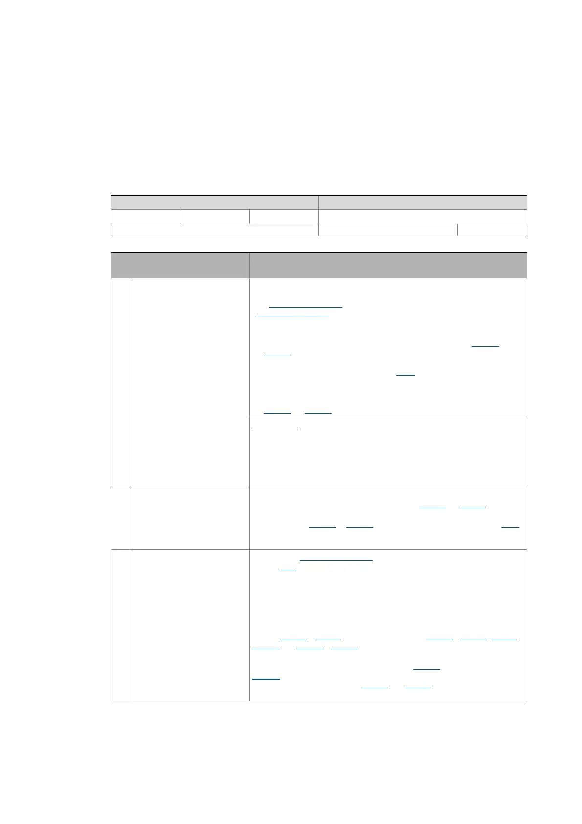
0x605E | 0x685E - Response to error
From version 01.05
Selection of the response to errors of class II:
-2 = quick stop if possible, otherwise DC current or short-circuit braking.
0 = pulse inhibit
2 = quick stop
Further information on the respective response can be found in the "Info" column further down.
Setting range (min. value | unit | max. value) Lenze setting
-32768 32767 -2
Write access CINH OSC P RX TX INTEGER_16
Setting/response in the event of an
error
Info
-2 Quick stop if possible,
otherwise DC current or short-
circuit braking
In case of servo control, first quick stop is activated as error response. If an
encoder error is detected here, ASM servo control immediately switches to
the "DC-injection braking
" and SM servo control immediately switches to the
"short-circuit braking
" function.
• This setting is reasonable for drives without service brake and with
limited travel way.
• The braking is maintained for the entire monitoring time (0x2826
or
0x3026
for axis B) since a standstill of the motor cannot be recognised
due to the missing feedback.
• Afterwards, the drive changes to the "Fault
" device status and inhibits the
inverter. If a holding brake is parameterised and connected, it will be
applied.
• The braking current for DC-injection braking (ASM) has to be set in
0x2B80
(or 0x3380 for axis B).
Background:
The servo control requires a feedback of position/speed signals
of the motor encoder. This basic condition also applies when the "quick stop"
function is activated. If the i700 servo inverter has no access to this
information anymore, it cannot realise a guided operation of the motor into
the drift-free standstill. When synchronous motors are operated, the i700
servo inverter loses the current pole position in addition, which can lead to a
non-guided behaviour.
2 Quick stop Quick stop is activated as error response.
• The deceleration for quick stop can be set in 0x6085
(or 0x6885 for axis B).
• After the deceleration has stopped or the monitoring time for quick stop
has elapsed (0x2826
or 0x3026 for axis B), the drive changes to the "Fault"
device status and inhibits the inverter. If a holding brake is parameterised
and connected, it will be applied.
0 Disable voltage Evading the "Fault reaction active
" device status, it is immediately changed
to the "Fault
" device status.
• The drive is immediately switched off (pulse inhibit).
• Thus the behaviour is identical to the behaviour in case of fatal errors
(class I).
Up to and including version 1.6.3:
Triggering the quick stop causes the drive to be stopped along the current
limit of 0x6073
/ 0x6873. The torque limits from 0x60E0 / 0x68E0, 0x60E1 /
0x68E1
and 0x6072 / 0x6872 are not effective during the quick stop!
From version 1.7.0
During the quick stop, both the current limit 0x6073
and the torque limit
0x6072
are active. The smaller of the two limits determine the output motor
torque. The torque limits from 0x60E0
and 0x60E1 have no effect during the
quick stop.

 Loading...


