Lenze · i700 servo inverter · reference manual · DMS 3.0 EN · 06/2016 · TD06 244
7 CiA402 device profile
7.11 Touch probe (TP)
_ _ _ _ _ _ _ _ _ _ _ _ _ _ _ _ _ _ _ _ _ _ _ _ _ _ _ _ _ _ _ _ _ _ _ _ _ _ _ _ _ _ _ _ _ _ _ _ _ _ _ _ _ _ _ _ _ _ _ _ _ _ _ _
7.11.3 Filtering the touch probe signal
A common filter time (debounce time) can be parameterised for the touch probe inputs in order to
debounce the TP signals so that there is no response to external interference signals.
• Every 31 μs, the signal status at the TP input is detected for the debounce filter and a new value
is assigned to the filter.
• Via the following object, the filter time for all touch probe inputs of both axes of the device is
set. A separate setting for a touch probe or an axis is not possible.
0x2500 - Touch probe (TP): Debounce time
7.11.4 Compensation of runtime delays
In reality, both the input connection in the i700 servo inverter and the touch probe sensor have
runtime delays (latencies) themselves. They can be taken into consideration for calculating the
actual tripping time and thus the actual position at the time of tripping.
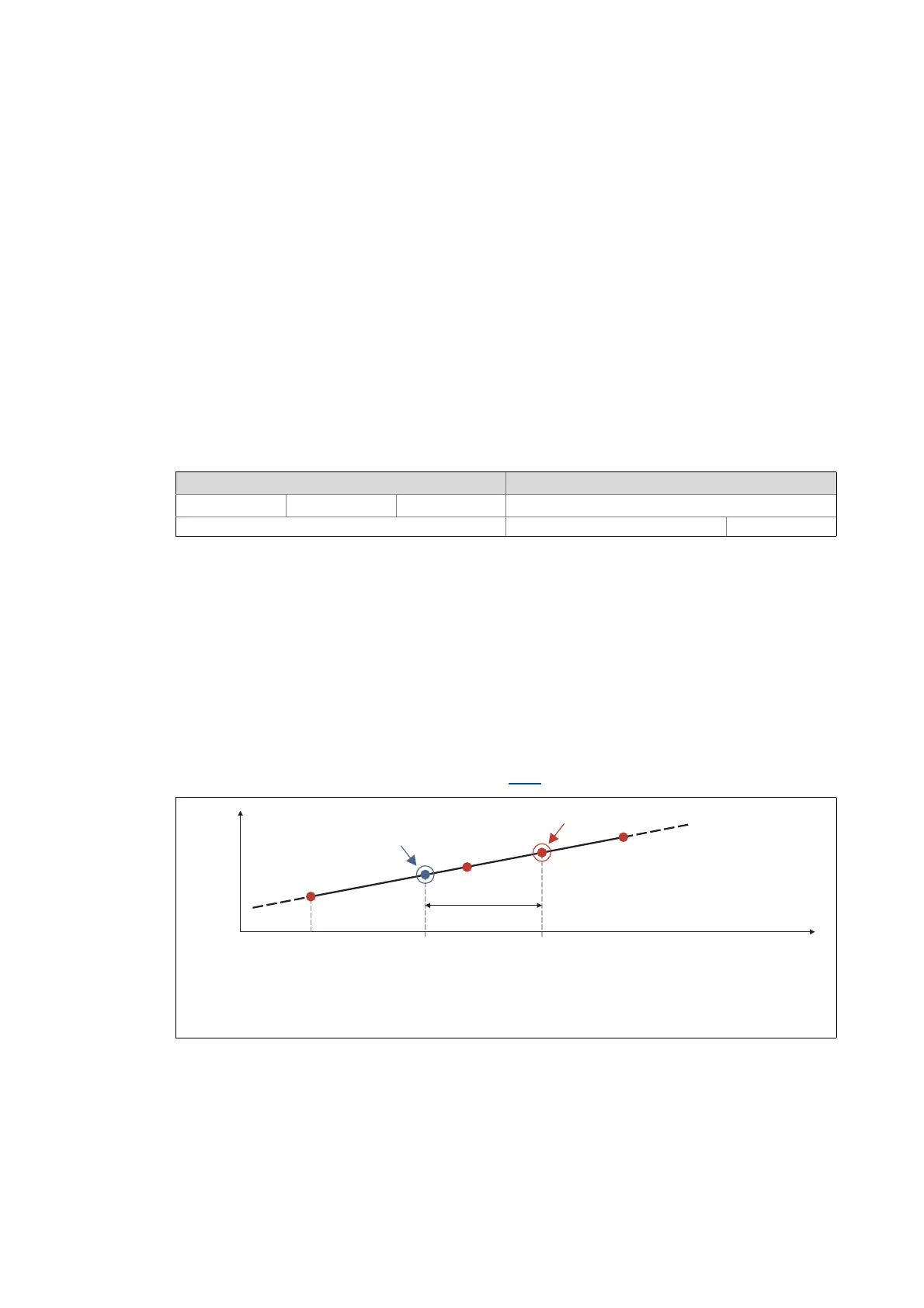
In the following illustration, the event is detected at the time in the i700 servo inverter. Due to
the input connection and the sensor used, however, the signal has undergone a runtime delay; the
actual physical event has already occurred at the time . In order to compensate this runtime delay,
a corresponding delay time which is taken into consideration for the determination of the control
cycle and interpolation of the position (see figure [7-9]
) can be set for each touch probe channel.
[7-10] Compensation of runtime delays (principle)
Note: Since the filter is scanned with 32 kHz, there are discrete, adjustable values. After entering an optional filter
time between 0 and 1984 μs, the value is automatically internally rounded down to the next adjustable value and
is also displayed on read request.
• The filter time is automatically taken into consideration in the TP calculation.
• If the setting is "0", the filter is deactivated.
Setting range (min. value | unit | max. value) Lenze setting
0 us 1984 0 us
Write access CINH OSC P RX TX UNSIGNED_16
Actual physical event
Electrical recognition of the event in the i700 servo inverter
Delay time between the actual physical event and the electrical recognition
Position
t
p
n-1
p
n
Event received
01
Event
p
n-2
Delay time

 Loading...


