Lenze · i700 servo inverter · reference manual · DMS 3.0 EN · 06/2016 · TD06 300
9 Diagnostics & error management
9.6 Diagnostics parameters
_ _ _ _ _ _ _ _ _ _ _ _ _ _ _ _ _ _ _ _ _ _ _ _ _ _ _ _ _ _ _ _ _ _ _ _ _ _ _ _ _ _ _ _ _ _ _ _ _ _ _ _ _ _ _ _ _ _ _ _ _ _ _ _
9.6 Diagnostics parameters
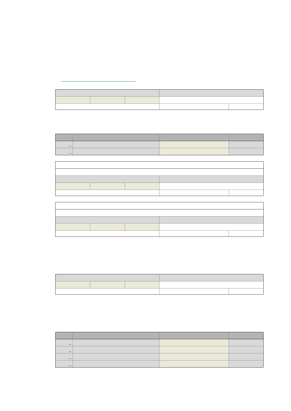
0x10F8 - ECAT DC: Current time
0x2D81 | 0x3581 - Counter: Operating time
0x2D82 | 0x3582 - motor: Actual voltage - Veff, phase-phase
0x2D83 | 0x3583 - Motor: Phase currents
Display of the time information the i700 servo inverter is currently using (time of the device if you will).
Real-time information (Distributed Clock)
Display area (min. value | unit | max. value) Initialisation
0 ns 2
64
-1
Write access CINH OSC P RX TX UNSIGNED_64
Sub. Name Lenze setting Data type
1 Device: Operating time UNSIGNED_32
2 Device: Power-on time UNSIGNED_32
Subindex 1: Device: Operating time
Display of the seconds the i700 servo inverter has been operated (device status "Operation enabled") so far.
Display area (min. value | unit | max. value) Initialisation
0 s 4294967295
Write access CINH OSC P RX TX UNSIGNED_32
Subindex 2: Device: Power-on time
Display of the seconds the i700 servo inverter has been switched on so far.
Display area (min. value | unit | max. value) Initialisation
0 s 4294967295
Write access CINH OSC P RX TX UNSIGNED_32
Display of the current motor voltage
Display area (min. value | unit | max. value) Initialisation
0.0 V 429496729.5 0.0 V
Write access CINH OSC P RX TX Scaling: 1/10 UNSIGNED_32
Display of the current motor current of each individual motor phase
Sub. Name Lenze setting Data type
1 Zero system current INTEGER_32
2 Current - phase U INTEGER_32
3 Current - phase V INTEGER_32
4 Current - phase W INTEGER_32

 Loading...


