Lenze · i700 servo inverter · reference manual · DMS 3.0 EN · 06/2016 · TD06 45
4 Device settings
4.1 Behaviour in case of error
_ _ _ _ _ _ _ _ _ _ _ _ _ _ _ _ _ _ _ _ _ _ _ _ _ _ _ _ _ _ _ _ _ _ _ _ _ _ _ _ _ _ _ _ _ _ _ _ _ _ _ _ _ _ _ _ _ _ _ _ _ _ _ _
4 Device settings
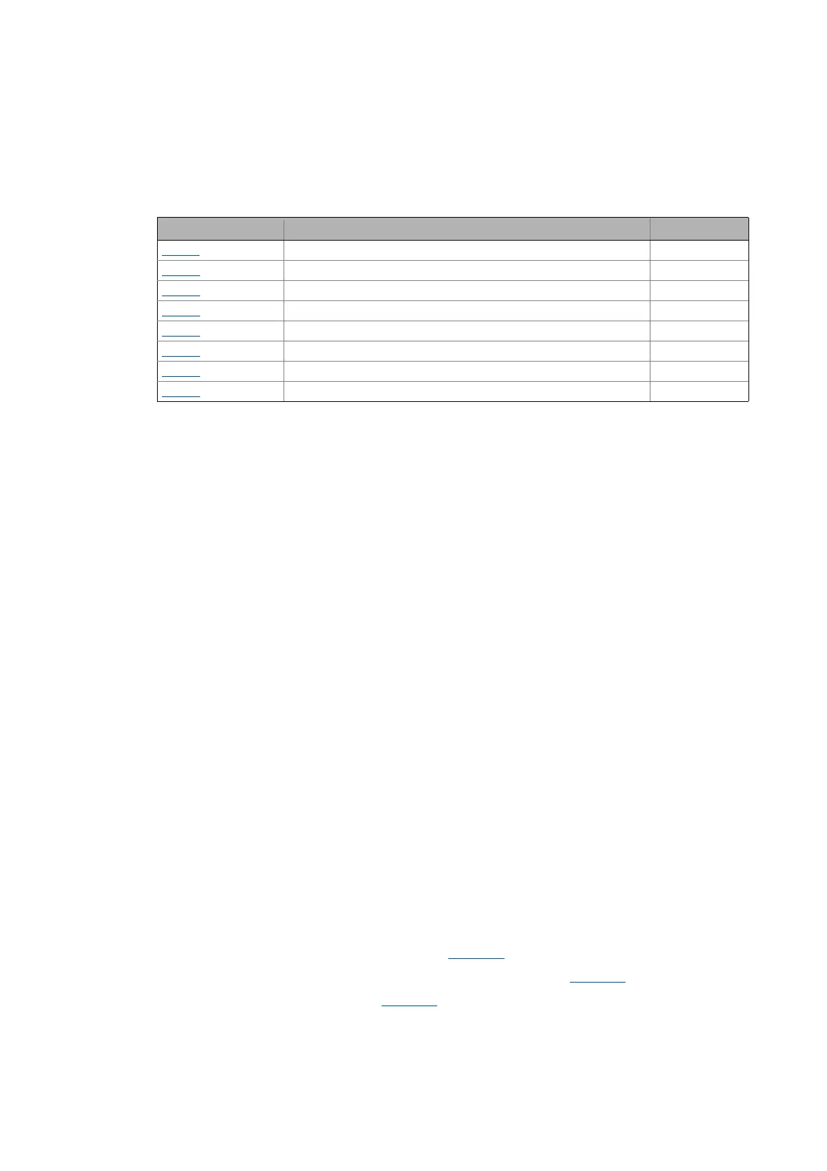
Objects described in this chapter
4.1 Behaviour in case of error
The i700 servo inverter features three different EtherCAT monitoring modes:
• Sync0 monitoring when DC mode is used
• PDO frame failure detection when DC mode is used
• Monitoring to EtherCAT line interruption
Sync0 monitoring when DC mode is used
This monitoring mode checks whether the Sync0 Signals are generated at the correct time in the
i700 servo inverter if the "Distributed Clock mode" (DC mode) has been selected and the i700 servo
inverter is in the "Operational" status.
• If no Sync0 signals arrive anymore during double the Sync0 cycle time, the i700 servo inverter
changes to the "Safe-Operational" status and triggers an error (CiA402 error code 0x8700). 0x32
is returned as bus status (AL status code).
• After "Pre-Operational" has changed to "Safe-Operational", the generation of Sync0 pulses has
to be started within 5 seconds. If this is not the case, or if a change from "Safe-Operational" to
"Operational" is requested without the signals being generated accordingly, this error is
triggered as well.
• This monitoring mode cannot be configured.
PDO frame failure detection when DC mode is used
This monitoring mode checks whether an EtherCAT-PDO telegram (Sync Manager 2 Event) has
arrived between two Sync0 signals if the "Distributed Clock mode" (DC mode) has been selected. For
this purpose, the i700 servo inverter is provided with an internal frame failure error counter which
is increased by the value "3" in case of a frame failure. For every PDO received correctly, the error
counter is reduced by the value "1".
This monitoring mode can be configured via the 0x10F1:2
object:
• From version 01.04, monitoring is activated in the Lenze setting (0x10F1:2
="20").
• If a value higher than "0" is set in 0x10F1:2
: If the internal frame failure error counter reaches
the set value, the i700 servo inverter changes to the "Safe-Operational" status and triggers an
error (CiA402 error code 0x8700).
Object Name Data type
0x10F1
ECAT: Behaviour in case of error RECORD
0x2000
Device: Data RECORD
0x2001
Device: Name STRING(128)
0x2021
Device: Optical recognition RECORD
0x2022
Device command UNSIGNED_32
0x2100
Brand protection INTEGER_32
0x2540
Device: Voltage values RECORD
0x2580
ECAT DC: Real-time information RECORD

 Loading...


