Lenze · i700 servo inverter · reference manual · DMS 3.0 EN · 06/2016 · TD06 64
5 Motor control & motor settings
5.3 Wiring check by means of manual test modes
_ _ _ _ _ _ _ _ _ _ _ _ _ _ _ _ _ _ _ _ _ _ _ _ _ _ _ _ _ _ _ _ _ _ _ _ _ _ _ _ _ _ _ _ _ _ _ _ _ _ _ _ _ _ _ _ _ _ _ _ _ _ _ _
5.3 Wiring check by means of manual test modes
Before the parameterisation of the actual control is started, the wiring of the motor (power and
encoder connection) should be checked for errors and function and, if required, should be corrected.
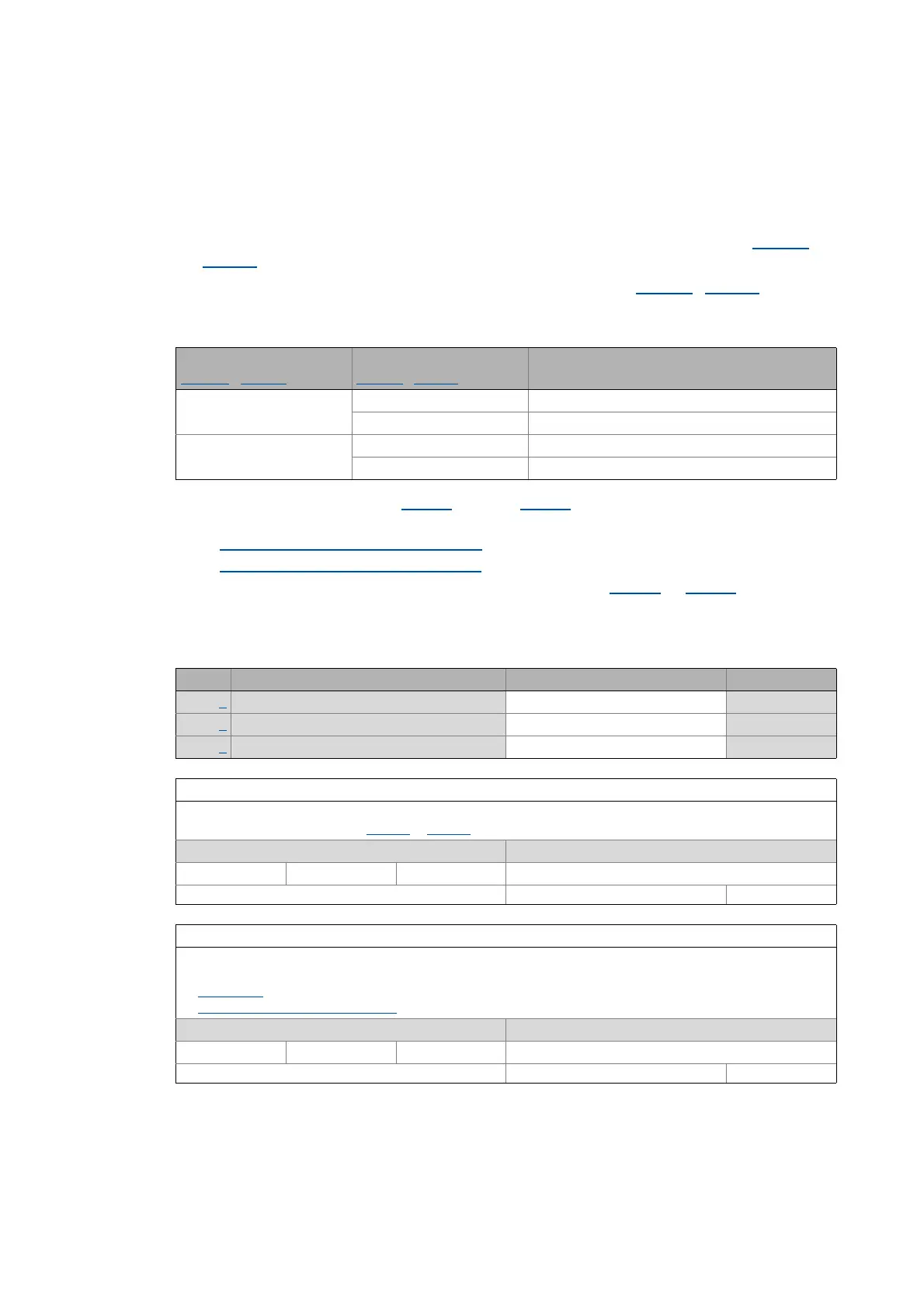
1. Provided that there is a in-phase motor connection and a positive field frequency (0x2DDD
/
0x35DD
), the motor shaft rotates clockwise.
2. An existing speed feedback (motor encoder) in the rotor position (0x2DDD
/ 0x35DD) generates
a numerical value with positive counting direction.
If necessary, take the following measures:
3. After controller inhibit via the 0x2825
object (or 0x3025 for axis B), the following test modes are
available for activation:
• Manual test mode "voltage/frequency"
• Manual test mode "current/frequency"
The parameters for the test modes can be adapted via object 0x2835 (or 0x3035 for axis B). For
this, observe the notes in the description of the respective test mode.
0x2835 | 0x3035 - Manual test mode: Settings
Field frequency
0x2DDD
/ 0x35DD
Display
0x2DDE
/ 0x35DE
Measure
CW 0 ... 2047 none
2047 ... 0 Correct motor cable / encoder cable
CCW 2047 ... 0 none
0 ... 2047 Correct motor cable / encoder cable
Sub. Name Lenze setting Data type
1 Manual test mode: Current setpoint 0 % INTEGER_16
2 Manual test mode: Frequency 0.0 Hz INTEGER_16
3 Manual test mode: Starting angle 0.0 ° INTEGER_16
Subindex 1: Manual test mode: Setpoint current
Selection of the r.m.s. value of a phase current for test mode
•100% ≡ rated motor current (0x6075
or 0x6875 for axis B)
Setting range (min. value | unit | max. value) Lenze setting
0 % 1000 0 %
Write access CINH OSC P RX TX INTEGER_16
Subindex 2: Manual test mode: Frequency
Selection of the frequency for test mode
Please observe the notes regarding the limitation of the output frequency in the chapters
• Manual jog
• Limitation of the output frequency
Setting range (min. value | unit | max. value) Lenze setting
-1000.0 Hz 1000.0 0.0 Hz
Write access CINH OSC P RX TX Scaling: 1/10 INTEGER_16

 Loading...


