Lenze · i700 servo inverter · reference manual · DMS 3.0 EN · 06/2016 · TD06 118
5 Motor control & motor settings
5.11 Setting control loops
_ _ _ _ _ _ _ _ _ _ _ _ _ _ _ _ _ _ _ _ _ _ _ _ _ _ _ _ _ _ _ _ _ _ _ _ _ _ _ _ _ _ _ _ _ _ _ _ _ _ _ _ _ _ _ _ _ _ _ _ _ _ _ _
5.11.1.1 Manual test mode "Current pulse"
The current controller must be adapted to the electrical characteristics of the motor – stator
resistance and stator inductance. For an experimental adjustment, the manual test mode "Current
pulse" can be used.
Functional description
In the manual "Current pulse" test mode, setpoint step-changes are applied to the current controller
input after controller enable. The step responses then either have to be recorded using the
oscilloscope and clamp-on ammeter, or by means of the i700 servo inverter oscilloscope function.
By evaluating the step responses, it is the objective to optimise the two current controller
parameters "gain" and "reset time" so that a quick current characteristic free of harmonics is
obtained. (See the following instructions.)
Motors with individual pole windings, which can feature very distinct saturation phenomena in the
stator leakage inductance, satisfactory results are possibly only achieved with a current-dependent
correction of the current controller parameters. For this purpose, a characteristic is stored in the i700
servo inverter, describing the current dependence of the stator leakage inductance and correcting
the current controller gain. Correction of the stator leakage inductance (Lss)...
Motor phase U is supplied with a DC current, the level of which is determined via the following
equation on the left. Motor phases V and W then carry half of this DC current, respectively (negative;
from the motor).
Note!
This test mode is intended for the adjustment of the current controller in the "servo
control for synchronous motor/asynchronous motor" mode and not for the adjustment
of the Imax controller in the "V/f characteristic control (VFC)" mode!
Stop!
In the case of the synchronous motor, a jerky compensating movement occurs after
controller enable if the pole position of this movement does not correspond to the
starting angle.
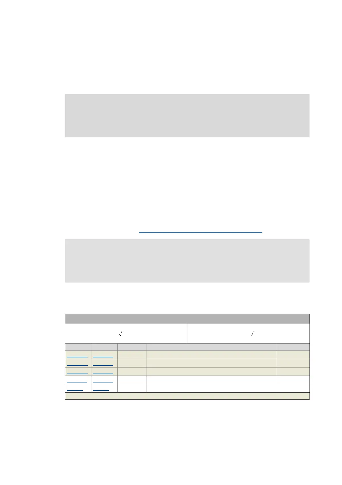
Equations for calculating the DC currents in motor phases U, V, W
Axis A Axis B Symbol Description Dimension unit
0x2D83:2 0x3583:2 I
phase_U
Present current in motor phase U A
0x2D83:3 0x3583:3 I
phase_V
Present current in motor phase V A
0x2D83:4 0x3583:4 I
phase_W
Present current in motor phase W A
0x2835:1
0x3035:1 I
test
Setpoint current for manual test mode %
0x6075
0x6875 I
rated
Rated motor current A
Greyed out = read access only
I
phase_U
2I
test
[%]
I
rated
100 %
---------------
⋅⋅=
I
phase_V, _W
-0.5 2 I
test
[%]
I
rated
100 %
---------------
⋅⋅ ⋅=

 Loading...


