Lenze · i700 servo inverter · reference manual · DMS 3.0 EN · 06/2016 · TD06 96
5 Motor control & motor settings
5.9 Setting the feedback system for the servo control
_ _ _ _ _ _ _ _ _ _ _ _ _ _ _ _ _ _ _ _ _ _ _ _ _ _ _ _ _ _ _ _ _ _ _ _ _ _ _ _ _ _ _ _ _ _ _ _ _ _ _ _ _ _ _ _ _ _ _ _ _ _ _ _
5.9.5 Additional settings for SinCos absolute value encoders with HIPERFACE® protocol
Absolute value encoders are especially suitable for:
• Synchronous motors operated in the "servo control" mode. The synchronous motor (SM) servo
control requires a pole position angle. This has to be detected only once during commissioning
and saved as offset towards the absolute position in the axis data.
• Positioning modes in which homing is to be carried out only once.
The analog evaluation of the sin/cos tracks causes a high resolution. With regard to the storage of
the position information, we distinguish between singleturn and multiturn encoders:
• Singleturn: Storage within one revolution
• Multiturn: Storage within a number of revolutions
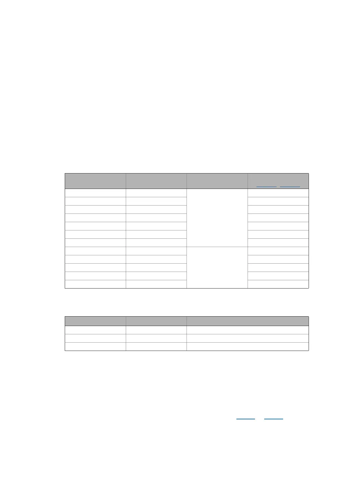
Supported encoder types with HIPERFACE® protocol
The following encoder types are supported by the i700 servo inverter:
Supported SinCos encoder types without HIPERFACE® protocol
The following encoder types are supported by the i700 servo inverter:
Use of non-supported encoder types
If an encoder is to be used, the type code of which is not listed in the table of the supported encoder
types, this encoder can be introduced to the i700 servo inverter via the subindices 2 and 3 of the
hiperface parameters described in the following. Please also observe the notes in the description of
subindex 8.
Reading data out of the encoder
The "Determine data of the Hiperface encoder" function in the object 0x2822
(or 0x3022 for axis B)
serves to read the type code, number of increments and number of distinguishable revolutions out
of the encoder and automatically enter then into the corresponding Hiperface parameters.
Type Increments/revolution Absolute revolutions Type code
(0x2C41:1
| 0x3441:1)
AM1024-8V-H (SRM50) 1024 4096
(Multiturn)
39
AM1024-8V-H (SFM60) 1024 39
AM1024-8V-K2 (SRM50S) 1024 39
AM128-8V-H (SKM36) 128 55
AM16-8V-H (SEL37) 16 71
AM16-8V-H (SEL52) 16 71
AM512-8V-H (SCM70) 512 7
AS1024-8V-H (SRS50) 1024 1
(Singleturn)
34
AS1024-8V-K2 (SRS50S) 1024 34
AS16-8V-H (SEK37) 16 66
AS16-8V-H (SEK52) 16 66
AS512-8V-H (SCS70) 512 2
Type Increments/revolution Absolute revolutions
IG1024-5V-V3 (RVS58S) 1024 0
IG2048-5V-S (ITD22) 2048 0
IG2048-5V-S 2048 0

 Loading...


