EasyManua.ls Logo

Lenze i700 User Manual

Lenze i700
359 pages
To Next Page IconTo Next Page
To Previous Page IconTo Previous Page
Page #35 background imageLoading...
Page #35 background image
3 Communication with the controller
3.6 Ethernet over EtherCAT (EoE)
35
Lenze · i700 servo inverter · reference manual · DMS 3.0 EN · 06/2016 · TD06
_ _ _ _ _ _ _ _ _ _ _ _ _ _ _ _ _ _ _ _ _ _ _ _ _ _ _ _ _ _ _ _ _ _ _ _ _ _ _ _ _ _ _ _ _ _ _ _ _ _ _ _ _ _ _ _ _ _ _ _ _ _ _ _
3.6.4.1 Structure of the EtherCAT data telegram
The GCI protocol is used for communication.
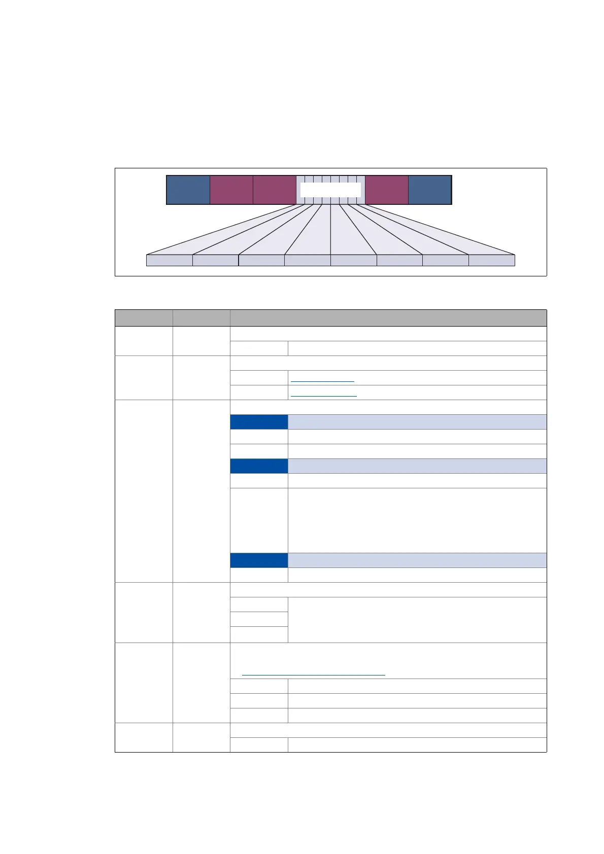
The EtherCAT data telegram is shown below. Here, the GCI header represents the part of the
program that is independent of the type of command transmitted.
[3-2] Structure of the GCI header within the EtherCAT frame
EtherCAT
Header
IP Header
TCP/IP
Header
GCI Header
P0 ... P4
EtherCAT
Footer
GMQGMT GSV GTI SIZE SIZE res res
Field Size Description
GMT 1 byte GCI message type
0x01 Reserved
GSV 1 byte GCI service identification
0x82 Read parameters
0x83 Write parameters
GMQ 1 byte GCI message qualifier
Bit 7 rsp (Request/Response)
0Request
1Response
Bit 6 a (Abort)
0 Data transfer OK
1 Abort of the data transfer
The transfer is either aborted by the client or the server of a
parameter data telegram.
A message is aborted without any confirmation. If the client waits
for its message to be confirmed, it will receive the abort notice
instead.
Bit 5 ... bit 0 res (reserved)
0b000000 Data contents = 0
GTI 1 byte GCI transaction ID
0x00 Serial number (transaction identification)
For each client a definite serial number (0 ... 255) is allocated.
The serial number in the multitasking environment is used for
referencing to the calling tasks (reverse transaction).
...
0xFF
SIZE 2 bytes Length of the user data
The user data area or the data telegram contains the parameter data.
Assignment of user data areas P0 ... P4
0x14 20 bytes
... ...
0x114 276 bytes
res 2 bytes Reserved
0x0000 Data contents = 0

Table of Contents

Other manuals for Lenze i700

Question and Answer IconNeed help?

Do you have a question about the Lenze i700 and is the answer not in the manual?

Lenze i700 Specifications

General IconGeneral
Control TypeVector control, V/f control
SafetySTO (Safe Torque Off)
Protection ClassIP20
Frequency50/60 Hz
Communication InterfacesCANopen
CoolingAir cooled
Protection FeaturesOvervoltage, Undervoltage
Ambient Temperature-10°C to +45°C
Frequency Range0 Hz to 300 Hz
Supply Voltage3-phase AC

Summary

About this documentation

Parameter handling

Parameter transfer during initialisation

Details the exchange of configuration data between the controller and the servo inverter during system acceleration.

Storage parameter set (par001.*) and total parameter set (par000.*)

Explains the two types of parameter sets provided for storage and their differences.

Communication with the controller

Acceleration of the system (initialisation)

Explains the process of establishing communication and the configuration data exchanged.

Ethernet over EtherCAT (EoE)

Describes the Ethernet over EtherCAT protocol for sending Ethernet telegrams via EtherCAT.

Device settings

Behaviour in case of error

Details the three EtherCAT monitoring modes for error detection.

Monitoring of the DC-bus voltage

Explains the monitoring of DC-bus voltage for undervoltage and overvoltage conditions.

Motor control & motor settings

Required commissioning steps (short overview)

Provides an overview of commissioning steps for different control modes and motor types.

Commissioning functions (short overview)

Details functions for automatic parameter calculation and setting for quick commissioning.

Wiring check by means of manual test modes

Explains how to check motor wiring and function using manual test modes.

Manual control

Describes the manual operation mode via engineering tools for wiring checks.

Setting the control mode

Explains the different modes for open-loop/closed-loop motor control supported by the i700 servo inverter.

Setting the motor parameters for the servo control

Guides on setting motor model parameters for servo control.

Setting the feedback system for the servo control

Explains how to set the feedback system for servo control after setting motor parameters.

Setting control loops

Details the setting of different control loops subsequent to motor parameterization.

Parameterising the V/f characteristic control

Covers the parameterization of the V/f characteristic control for motor voltage determination.

Holding brake control

CiA402 device profile

Device control

Explains objects that control the servo inverter states and operating modes.

Cyclic sync position mode (csp)

Explains the cyclic sync position mode, providing quick position following with speed/torque feedforward control.

Monitoring functions

Monitoring of the power section and device utilisation (Ixt)

Details the monitoring of device utilisation to protect the power section and other components.

Monitoring of the motor utilisation (I²xt)

Detects motor thermal utilisation by calculating thermal motor utilization from detected motor currents.

Monitoring of the position and velocity error

Monitors position and velocity errors against set tolerances.

Diagnostics & error management

CiA402 error codes / error messages

Lists possible error codes, their causes, remedies, and responses for the i700 servo inverter.

Related product manuals