Lenze · i700 servo inverter · reference manual · DMS 3.0 EN · 06/2016 · TD06 220
7 CiA402 device profile
7.8 Cyclic sync position mode (csp)
_ _ _ _ _ _ _ _ _ _ _ _ _ _ _ _ _ _ _ _ _ _ _ _ _ _ _ _ _ _ _ _ _ _ _ _ _ _ _ _ _ _ _ _ _ _ _ _ _ _ _ _ _ _ _ _ _ _ _ _ _ _ _ _
Tip!
For an interpolation cycle of 2 ms, for instance, the following values are to be set:
• Subindex 1 (Time period value) = "2"
• Subindex 2 (Time index) = "-3"
0x60E0 | 0x68E0 - Positive torque limit value
0x60E1 | 0x68E1 - Negative torque limit value
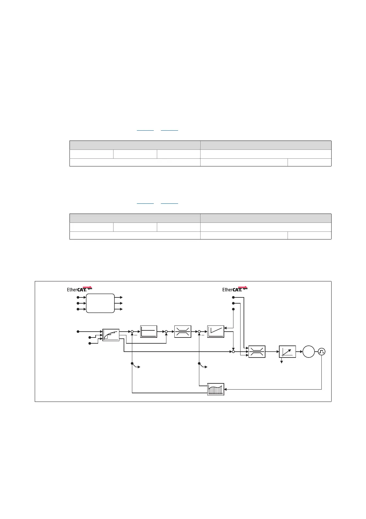
7.8.3 Signal flow
[7-5] Signal flow of the servo control in cyclic sync position mode (simplified representation)
100 % ≡ rated motor torque (0x6076 or 0x6876 for axis B)
Setting range (min. value | unit | max. value) Lenze setting
0.0 % 3276.7 100.0 %
Write access CINH OSC P RX TX Scaling: 1/10 UNSIGNED_16
100 % ≡ rated motor torque (0x6076 or 0x6876 for axis B)
Setting range (min. value | unit | max. value) Lenze setting
0.0 % 3276.7 100.0 %
Write access CINH OSC P RX TX Scaling: 1/10 UNSIGNED_16
Interpolation
I
q
I
d
M
CTRL
Target position
Velocity offset
Torque offset
Position
controller
Speed controller: Load value
Position actual value
Controlword
Lenze control word
Modes of operation
Statusword
Lenze status word
Modes of operation display
Positive torque limit value
Negative torque limit value
Speed
limitation
Speed
controller
Torque
limitation
Encoder
evaluation
Field-orientated
control
Torque actual valueVelocity actual value

 Loading...


