3 Communication with the controller
3.4 Activating the control via PDO
29
Lenze · i700 servo inverter · reference manual · DMS 3.0 EN · 06/2016 · TD06
_ _ _ _ _ _ _ _ _ _ _ _ _ _ _ _ _ _ _ _ _ _ _ _ _ _ _ _ _ _ _ _ _ _ _ _ _ _ _ _ _ _ _ _ _ _ _ _ _ _ _ _ _ _ _ _ _ _ _ _ _ _ _ _
3.4 Activating the control via PDO
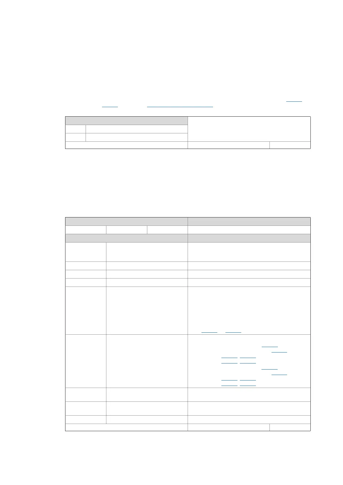
0x2824 | 0x3024 - Device control via PDO: Activation
3.5 Lenze control and status word
0x2830 | 0x3030 - Lenze control word
This object serves to switch off all RPDOs (from the device's point of view) so that the device is exclusively controlled
via SDOs.
• This is, for instance, required for manual enable of commissioning functions and test modes via the (0x6040
control word 0x6840
for axis B). Enable/inhibit via control word
Selection list (Lenze setting printed in bold)
0Off
1Activate
Write access CINH OSC P RX TX UNSIGNED_8
Via the Lenze control word, the control functions can be influenced.
Setting range (min. value | unit | max. value) Lenze setting
0x0000 0xFFFF 0x0000
Value is bit-coded: ( =bit set) Info
Bit 0 Flying restart: Completed Via this bit, the control reports the acceptance of the
speed found to the "Flying restart" function. The flying
restart process is now completed.
Bit 1 Flying restart: Blocked "1" ≡ Block flying restart process
Bit 2 Reserved
Bit 3 Reserved
Bit 4 Speed controller: Load I component "1" ≡ Set starting value of the torque
• In case of servo control, this corresponds to the I
component of the speed controller, in case of V/f
operation to the modulation of the slip
compensation.
• As long as this bit is set to "1", the I component and
the slip compensation are set to the starting value set
in 0x2902
(or 0x3102 for axis B).
Bit 5 Position: Select new actual position "1" ≡ Set/relatively shift actual position
• Axis A: Set the actual position (0x6064
) under
consideration of the set resolution (0x608F
) to the
value set in 0x2983
(0x2984 = 0), or shift it by the
value set in 0x2983
(0x2984 = 1).
• Axis B: Set the actual position (0x6864
) under
consideration of the set resolution (0x688F
) to the
value set in 0x3183
(0x3184 = 0), or shift it by the
value set in 0x3183
(0x3184 = 1).
Bit 6 Activate DC-injection braking or
short-circuit braking
"1" ≡ Trigger DC-injection braking for asynchronous
motor or short-circuit braking for synchronous motor
Bit 7 Velocity and position monitoring -
deactivated
Bit 8-15 Reserved
Write access CINH OSC P RX TX UNSIGNED_16

 Loading...


