5 Motor control & motor settings
5.9 Setting the feedback system for the servo control
91
Lenze · i700 servo inverter · reference manual · DMS 3.0 EN · 06/2016 · TD06
_ _ _ _ _ _ _ _ _ _ _ _ _ _ _ _ _ _ _ _ _ _ _ _ _ _ _ _ _ _ _ _ _ _ _ _ _ _ _ _ _ _ _ _ _ _ _ _ _ _ _ _ _ _ _ _ _ _ _ _ _ _ _ _
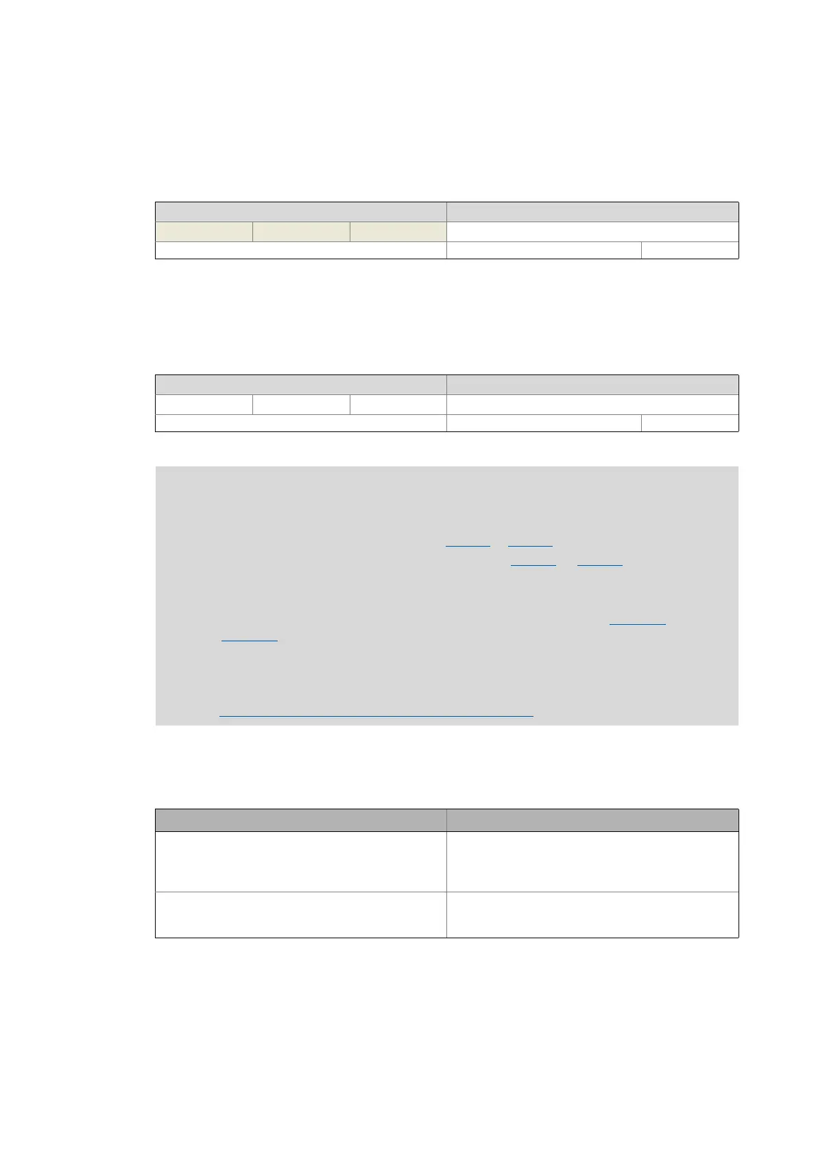
0x2C5F | 0x345F - Feedback system: Parameter CRC
5.9.2 Settings for "resolver" version
0x2C43 | 0x3443 - Resolver: Number of pole pairs
Resolver error compensation, resolover error identification
The actual position determined via the resolver does not exactly correspond to the actual physical
position. There will always be some greater or lesser deviation due to the following causes:
The i700 servo inverter provides the possibility to identify the error of the connected resolver and to
automatically generate adjustment values for compensating the resolver error.
Preconditions for the execution
• The motor is operated in speed open-loop control and servo control.
From version 01.03
Display area (min. value | unit | max. value) Initialisation
0 4294967295
Write access CINH OSC P RX TX UNSIGNED_32
Setting range (min. value | unit | max. value) Lenze setting
1101
Write access CINH OSC P RX TX UNSIGNED_8
Note!
Resolvers with a number of pole pairs > 1 are no absolute value encoders.
• Thus, bit 4 in the Lenze status word 2 (0x2833
or 0x3033 for axis B) remains set to "0".
• The "distinguishable revolutions" specification in 0x2C46
(or 0x3446 for axis B) is also
set to "0".
The following applies to synchronous motors:
• In case of integer ratios of the number of pole pairs of the motor (0x2C01:1
or
0x3401:1
for axis B) to the number of pole pairs of the resolver, the pole position
identification is only required once.
• In case of non-integer ratios, a pole position identification has to be executed after
every 24-V switching operation of the i700 servo inverter.
Synchronous motor (SM): Pole position identification
( 90)
Cause Remedy
The inductances of the sine and cosine track of the
resolver have slightly different values.
Adaptation of the gains for the digital-analog converters
supplying the resolver tracks.
• In the Lenze setting, the gains for both resolver tracks
are preset identically.
Sine and cosine track do not magnetise orthogonally to
each other.
Correction of the angle by means of which the two
resolver tracks are supplied in a manner relative to one
another.

 Loading...


