5 Motor control & motor settings
5.14 Parameterising the V/f characteristic control
151
Lenze · i700 servo inverter · reference manual · DMS 3.0 EN · 06/2016 · TD06
_ _ _ _ _ _ _ _ _ _ _ _ _ _ _ _ _ _ _ _ _ _ _ _ _ _ _ _ _ _ _ _ _ _ _ _ _ _ _ _ _ _ _ _ _ _ _ _ _ _ _ _ _ _ _ _ _ _ _ _ _ _ _ _
5.14.3 Setting the voltage boost
As an alternative for the voltage vector control, a constant, load independent voltage boost can be
specified for low speeds (below the V/f rated frequency) or for a motor standstill in order to optimise
the starting performance.
Depending on the required starting torque, the voltage boost must be set so that the required
motor current will be available after controller enable.
• The voltage boost can be calculated by multiplying the stator resistance by the rated
magnetising current:
• Optionally, the voltage boost can be determined empirically by increasing the setting until the
rated magnetising current flows.
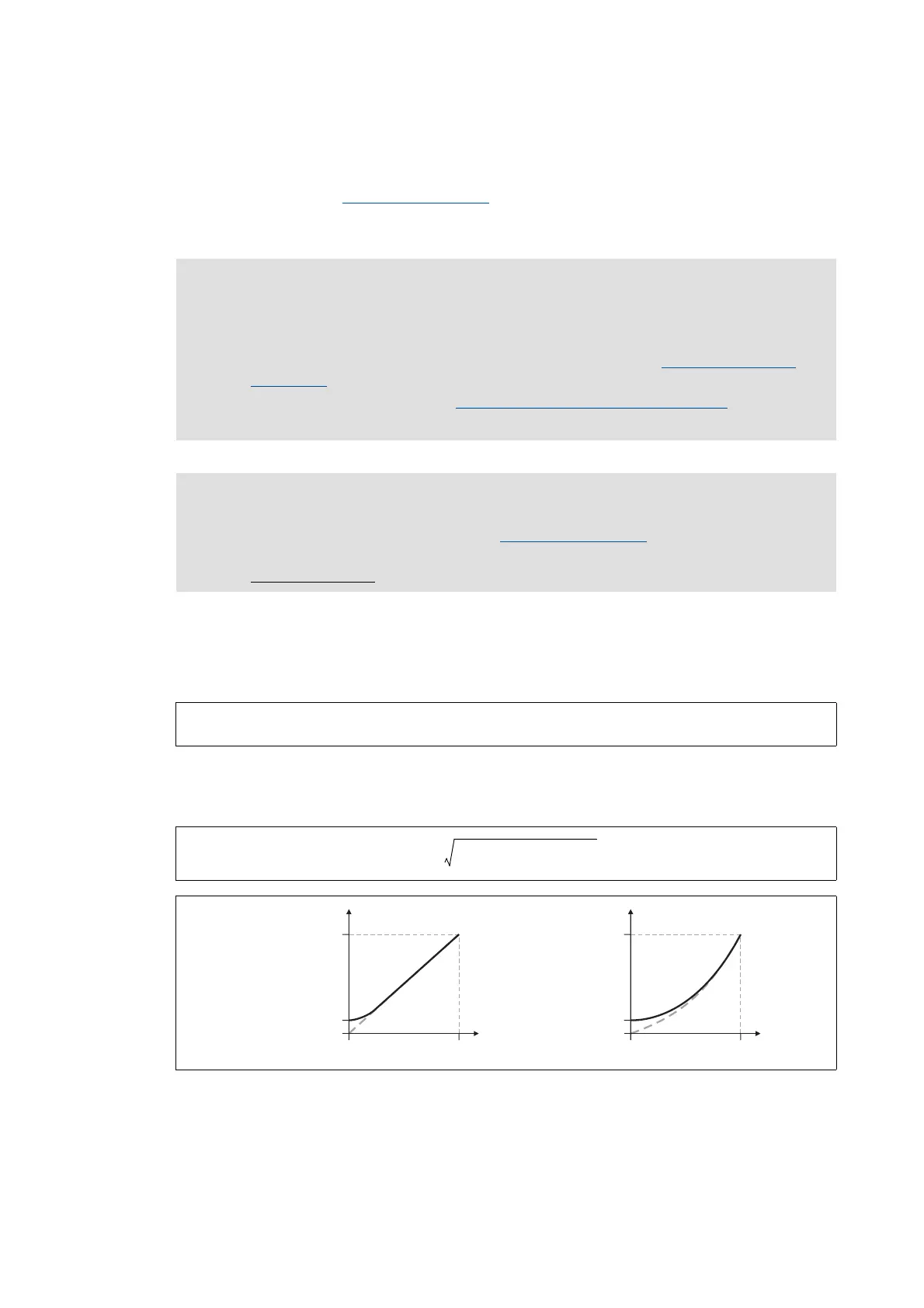
• The voltage boost is added geometrically to the voltage of the characteristic:
[5-13] Voltage boost for a linear V/f characteristic (left) and square-law V/f characteristic (right)
Stop!
If the motor is operated at standstill for a longer time - especially in case of smaller
motors - the motor can be destroyed by overtemperature!
• Connect the KTY of the motor. Parameterise and activate the Motor temperature
monitoring. ( 263)
• Parameterise and activate the Monitoring of the motor utilisation (I²xt)
. ( 254)
• Operate self-ventilated motors with a blower, if required.
Note!
The voltage boost acts additively to the voltage vector control.
• Only use one of the two "Boost" functions.
Recommendation:
voltage vector control
Starting current V
Boost
∼ R
S
I
mN
⋅=
UU
Characteristic
2
U
Boost
2
+=
0
0
U
Boost
0
0
U
Boost
f
set
VV
f
set
Frequency at ref. point
Voltage at ref. point Voltage at ref. point
Frequency at ref. point

 Loading...


