Lenze · i700 servo inverter · reference manual · DMS 3.0 EN · 06/2016 · TD06 110
5 Motor control & motor settings
5.10 Synchronous motor (SM): Pole position identification
_ _ _ _ _ _ _ _ _ _ _ _ _ _ _ _ _ _ _ _ _ _ _ _ _ _ _ _ _ _ _ _ _ _ _ _ _ _ _ _ _ _ _ _ _ _ _ _ _ _ _ _ _ _ _ _ _ _ _ _ _ _ _ _
How to execute the pole position identification PPI (min. movement):
1. If the servo inverter is enabled, inhibit the servo inverter.
Enable/inhibit operation via control word
( 52)
2. Set object 0x2825
(or 0x3025 for axis B) to "6" to change to the "Pole position identification
(min. movement)" operating mode.
3. Enable the servo inverter to start the procedure.
Note: By means of controller inhibit, the procedure started can be cancelled any time, if
required, without a change in settings.
After successful completion of the pole position identification...
...controller inhibit is set automatically and the pole position specified in object 0x2C03:2
(or
0x3403:2
for axis B) for the activated feedback system is set.
• For permanent storage, the changed settings must be uploaded to the controller from the i700
servo inverter.
The »EASY Starter« serves to save the parameter settings of the i700 servo inverter as parameter
file (*.gdc). In the »PLC Designer«, this file can then be imported in the corresponding axis.
Saving changed parameters safe against mains failure
( 53)
• The controller inhibit automatically set by the procedure can be deactivated via the
Controlword (0x6040
or 0x6840 for axis B).Enable/inhibit operation via control word ( 52)
Adapt pole position identification PPI (min. movement)
The above-described procedure for pole position identification can be adjusted to the respective
machine and the prevailing moments of inertia by means of the parameters described in the
following.
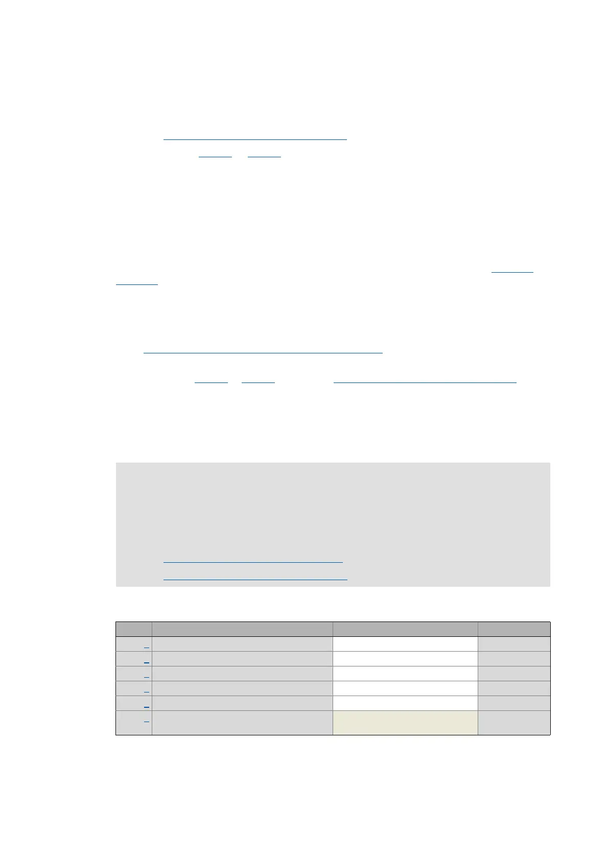
0x2C62 | 0x3462 - Pole position identification PPI (min. movement)
Stop!
If there is no temperature monitoring in the motor and/or the I²xt motor monitoring and
the maximum current monitoring are not parameterised correctly, the motor might be
damaged permanently when the current amplitude is set too high (e.g. to the maximum
value!
Monitoring of the motor utilisation (I²xt)
( 254)
Monitoring of the ultimate motor current
( 271)
Sub. Name Lenze setting Data type
1 PPI (min. movement): Current amplitude 25 % UNSIGNED_16
2 PPI (min. movement): Ramp time - current 10 s UNSIGNED_16
3 PPI (min. movement): Gain 0 % UNSIGNED_16
4 PPI (min. movement): Reset time 62.5 ms UNSIGNED_16
5 PPI (min. movement): Max. move permitted 20 ° UNSIGNED_8
6 PPI (min. movement): Absolute current
amplitude
UNSIGNED_32

 Loading...


