Lenze · i700 servo inverter · reference manual · DMS 3.0 EN · 06/2016 · TD06 80
5 Motor control & motor settings
5.8 Setting the motor parameters for the servo control
_ _ _ _ _ _ _ _ _ _ _ _ _ _ _ _ _ _ _ _ _ _ _ _ _ _ _ _ _ _ _ _ _ _ _ _ _ _ _ _ _ _ _ _ _ _ _ _ _ _ _ _ _ _ _ _ _ _ _ _ _ _ _ _
5.8.2.1 Enter motor nameplate data
If the equivalent circuit data of the motor required for the motor model are not known, they can
automatically be determined by approximation by the i700 servo inverter by means of the motor
nameplate data before they are set.
How to have the equivalent circuit data determined by the i700 servo inverter:
1. Set the complete motor nameplate data in object 0x2C01
(or 0x3401 for axis).
2. Set the rated motor current in object 0x6075
(or 0x6875 for axis B).
3. Set object 0x2822
(or 0x3022 for axis B) to "3" in order to have the equivalent circuit data
determined by approximation.
• The progress of the procedure is shown in object 0x2823
(or 0x3023 for axis B)
4. For permanent storage: Upload the set equivalent circuit data to the controller from the
i700 servo inverter after the procedure has been completed:
• For asynchronous motor (ASM): Object 0x2C02
(or 0x3402 for axis B).
• For synchronous motor (SM): Object 0x2C03
(or 0x3403 for axis B).
The »EASY Starter« serves to save the parameter settings of the i700 servo inverter as
parameter file (*.gdc). In the »PLC Designer«, this file can then be imported in the
corresponding axis. Saving changed parameters safe against mains failure
( 53)
5.8.2.2 Set motor parameters manually
If all required motor data are known (e.g. by means of a data sheet provided by the motor
manufacturer), they can be set manually in the following parameters:
Note!
This axis command serves to derive the scaled warning and switch-off thresholds of the
motor temperature monitoring from the parameterised insulation class (0x2C01:9
or
0x3401:9
). There are motor/device combinations, where the warning and switch-off
thresholds (0x2D49:3
/ 0x3549:3 or 0x2D49:4 / 0x3549:4) are assigned to a lower
insulation class (e.g. winding design in insulation class H, switch-off temperature
155 °C).
In this case, a manual parameterisation is required at the end of the motor
commissioning.
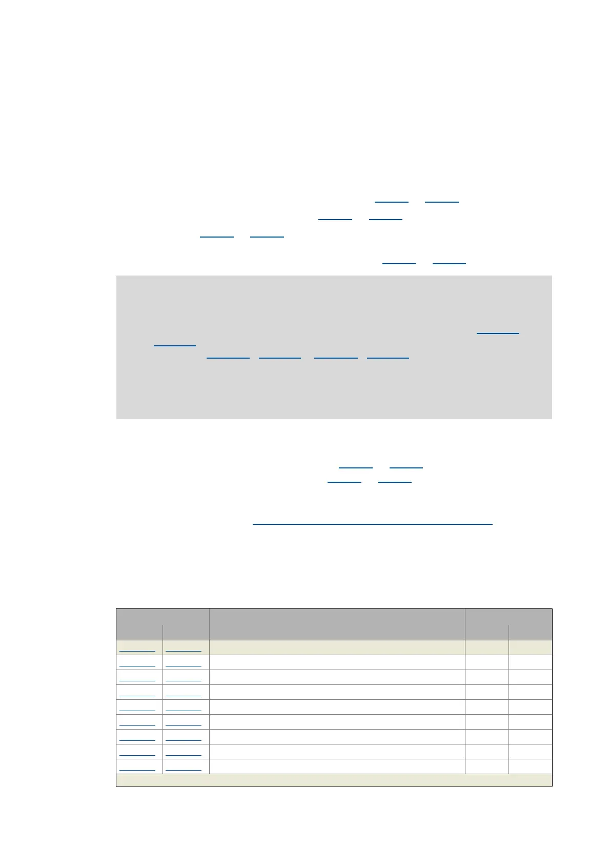
Object Name Required for
Axis A Axis B
SM ASM
0x2C01:1 0x3401:1 Motor: Number of pole pairs
0x2C01:2
0x3401:2 Motor: Stator resistance (value at 20°C)
0x2C01:3
0x3401:3 Motor: Stator leakage inductance
0x2C01:4
0x3401:4 Motor: Rated speed
0x2C01:5
0x3401:5 Motor: Rated frequency
0x2C01:6
0x3401:6 Motor: Rated power
0x2C01:7
0x3401:7 Motor: Rated voltage
0x2C01:8
0x3401:8 Motor: Rated cosine phi
0x2C01:9
0x3401:9 Motor: Insulation class
Greyed out = read access only

 Loading...


