Spectrum Measurements
R&S
®
ESR
226User Manual 1175.7068.02 ─ 12
lution bandwidth irrespective of the amplitude distribution, without additional correction
factors being required. The absolute measurement uncertainty of the R&S ESR is < 1.5
dB and a relative measurement uncertainty of < 0.5 dB (each with a confidence level of
95 %).
Measurement Methods
The channel power is defined as the integration of the power across the channel band-
width.
The Adjacent Channel Power Ratio (ACPR), also known as the Adjacent Channel
Leakage Power Ratio (ACLR), is defined as the ratio between the total power of the
adjacent channel to the carrier channel's power. An ACLR measurement with several
carrier (transmission) channels (TX channels) is also possible and is referred to as a
"multi-carrier ACLR measurement".
There are two possible methods for measuring channel and adjacent channel power
with a signal analyzer:
●
IBW method (Integration Bandwidth Method)
●
Zero-span method (Fast ACLR), i.e. using a channel filter
● IBW method.......................................................................................................... 226
● Fast ACLR.............................................................................................................227
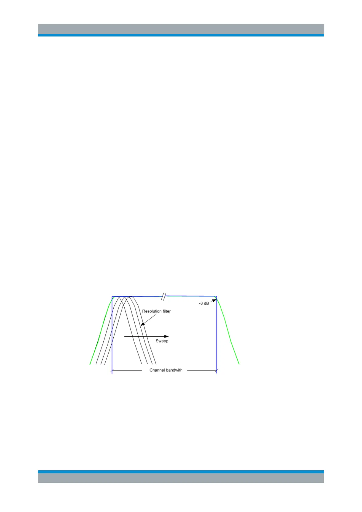
IBW method
When measuring the channel power, the R&S ESR integrates the linear power which
corresponds to the levels of the pixels within the selected channel. The signal analyzer
uses a resolution bandwidth which is far smaller than the channel bandwidth. When
sweeping over the channel, the channel filter is formed by the passband characteristics
of the resolution bandwidth (see Figure 6-1).
Figure 6-1: Approximating the channel filter by sweeping with a small resolution bandwidth
The following steps are performed:
1. The linear power of all the trace pixels within the channel is calculated.
P
i
= 10
(Li/10)
where P
i
= power of the trace pixel i
L
i
= displayed level of trace point i
Measurements
 Loading...


