Spectrum Measurements
R&S
®
ESR
434User Manual 1175.7068.02 ─ 12
Two signals with the same amplitude can be resolved if the resolution bandwidth is
smaller than or equal to the frequency spacing of the signal. If the resolution bandwidth
is equal to the frequency spacing, the spectrum display screen shows a level drop of 3
dB precisely in the center of the two signals. Decreasing the resolution bandwidth
makes the level drop larger, which thus makes the individual signals clearer.
If there are large level differences between signals, the resolution is determined by
selectivity as well as by the resolution bandwidth that has been selected. The measure
of selectivity used for signal analyzers is the ratio of the 60 dB bandwidth to the 3 dB
bandwidth (= shape factor).
For the R&S ESR, the shape factor for bandwidths is < 5, i.e. the 60 dB bandwidth of
the 30 kHz filter is <150 kHz.
The higher spectral resolution with smaller bandwidths is won by longer sweep times
for the same span. The sweep time has to allow the resolution filters to settle during a
sweep at all signal levels and frequencies to be displayed.
6.4.3.2 Intermodulation Measurements
If several signals are applied to a transmission two-port device with nonlinear charac-
teristic, intermodulation products appear at its output at the sums and differences of
the signals. The nonlinear characteristic produces harmonics of the useful signals
which intermodulate at the characteristic. The intermodulation products of lower order
have a special effect since their level is largest and they are near the useful signals.
The intermodulation product of third order causes the highest interference. It is the
intermodulation product generated from one of the useful signals and the 2nd harmonic
of the second useful signal in case of two-tone modulation.
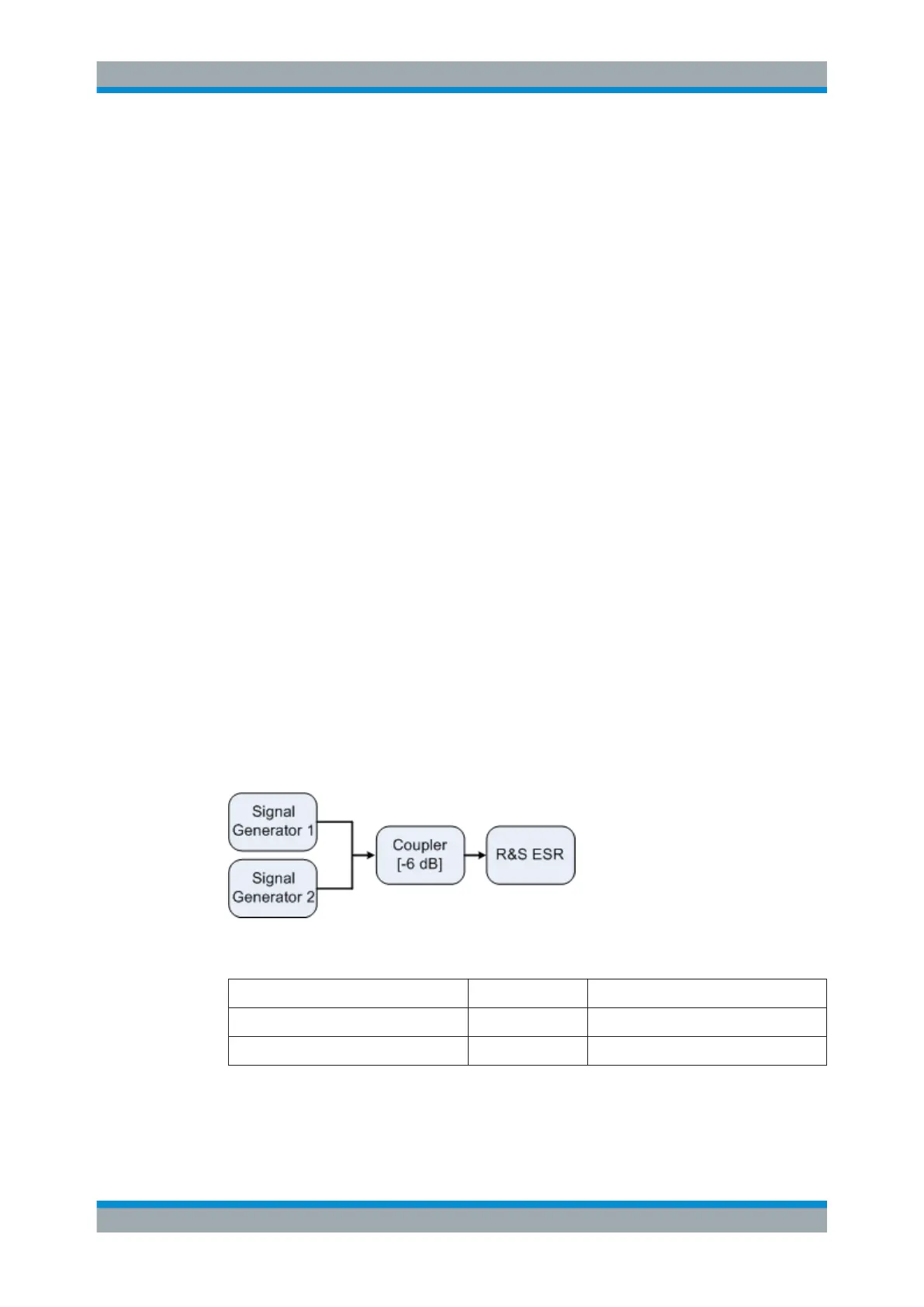
Measurement Example – Measuring the R&S ESR's Intrinsic Intermodulation
Test setup:
Signal generator settings (e.g. R&S SMW):
Level Frequency
Signal generator 1 -4 dBm 999.7 MHz
Signal generator 2 -4 dBm 1000.3 MHz
Setting up the measurement
1. Set the R&S ESR to its default settings by pressing the [PRESET] key.
Advanced Measurement Examples
 Loading...


