Spectrum Measurements
R&S
®
ESR
448User Manual 1175.7068.02 ─ 12
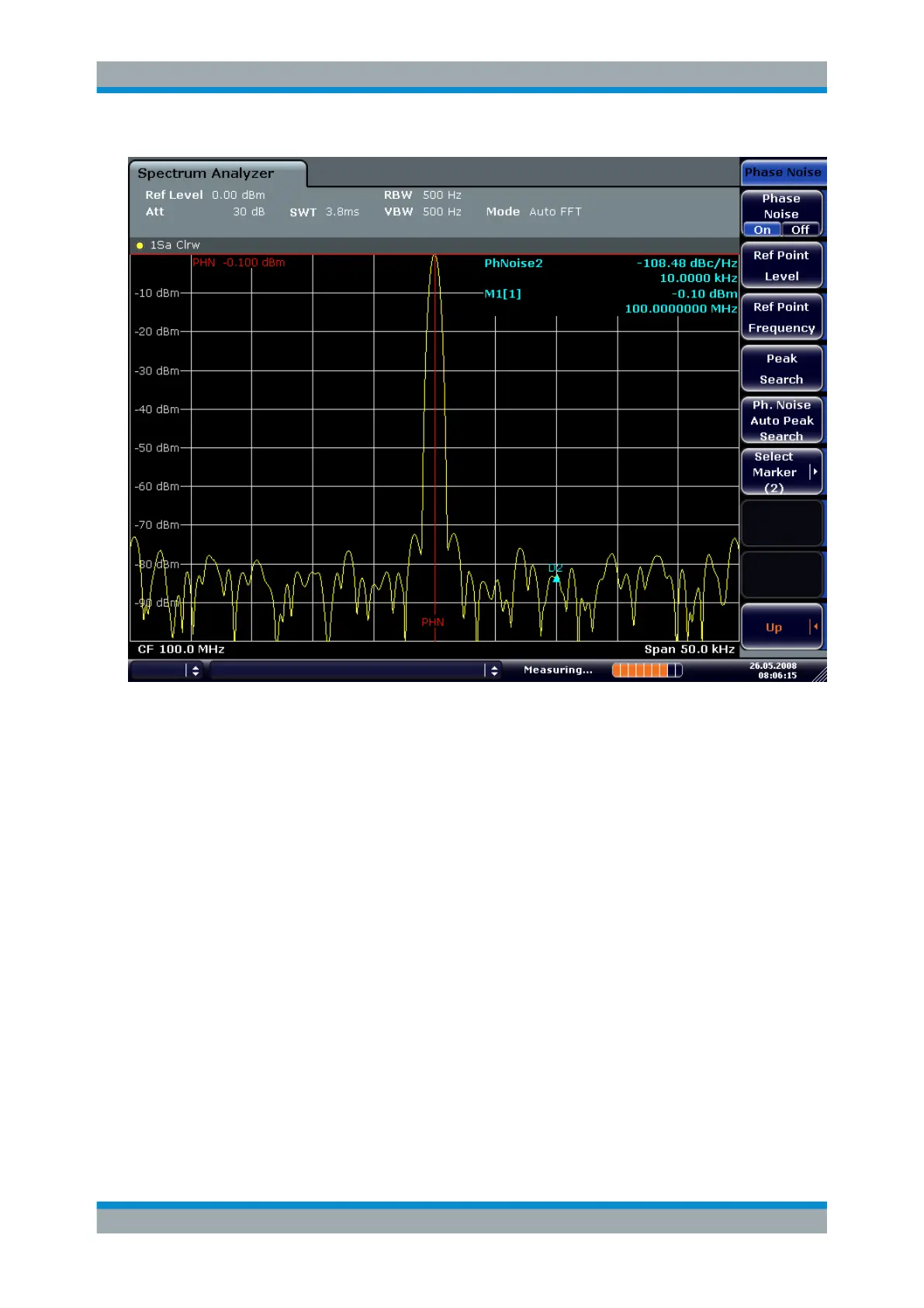
Figure 6-31: Measuring phase noise with the phase-noise marker function
The frequency offset can be varied by moving the marker with the rotary knob or by
entering a new frequency offset as a number.
6.4.6 Measurements on Modulated Signals
6.4.6.1 Measuring Channel Power and Adjacent Channel Power
Measuring channel power and adjacent channel power is one of the most important
tasks in the field of digital transmission for a signal analyzer with the necessary test
routines. While, theoretically, channel power could be measured at highest accuracy
with a power meter, its low selectivity means that it is not suitable for measuring adja-
cent channel power as an absolute value or relative to the transmit channel power. The
power in the adjacent channels can only be measured with a selective power meter.
A signal analyzer cannot be classified as a true power meter, because it displays the IF
envelope voltage. However, it is calibrated such as to correctly display the power of a
pure sine wave signal irrespective of the selected detector. This calibration cannot be
applied for non-sinusoidal signals. Assuming that the digitally modulated signal has a
Gaussian amplitude distribution, the signal power within the selected resolution band-
Advanced Measurement Examples
 Loading...


