Line connection and line-side power components
3.9 Active Interface Modules internal air cooling
Booksize Power Units
Manual, (GH2), 07/2016, 6SL3097-4AC00-0BP8
123
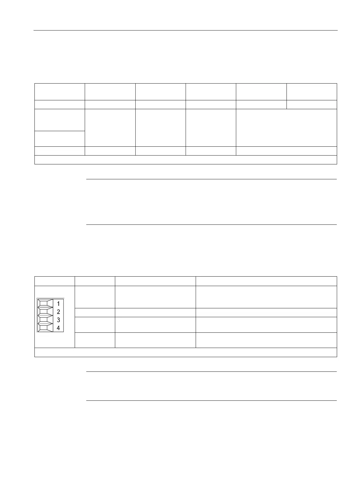
Table 3- 22 Line and load connection Active Interface Module
Line supply con-
nection
L1, L2, L3
Connector,
16 mm²,
1.7 Nm
Screw terminal
50 mm²,
end sleeve,
6 Nm
Screw terminal
50 mm²,
end sleeve,
6 Nm
Threaded bolt M8,
cross-section 120 / 2 x 50 mm²,
13 Nm
1)
Load connection
1)
For ring cable lugs without insulation (Page 732)
Note
Maintaining touch protection for Active Interface Modules 36 kW
T
he connection terminals of the 36 kW Active Interface Module are only certain to have
touch protection IPXXB according to IEC
60529, if cables with a minimum cross-section of
25 mm² and insulated end sleeves are used.
X121 temperature sensor and fan control
Table 3- 23 Plug-in screw terminal X121
1 +Temp Output temperature switch
Must be connected to interface X21 of the Active Line
Temperature switch output
3 +24 V power supply for digital
inputs
Current carrying capacity: 500 mA
4 Disable Fan
The fan can be disabled. The fan may be disabled only
while the Active Line Module is disabled.
Type: Screw terminal 1 (Page 730)
Note
If terminal X121.4 is not connected (or connected with low level), the fan will run in the
continuous mode.

 Loading...


