Line Modules Booksize
4.9 Smart Line Modules with internal air cooling
Booksize Power Units
272 Manual, (GH2), 07/2016, 6SL3097-4AC00-0BP8
Terminals X21.3 and X21.4
For operation, the 24 V DC voltage must be connected to terminal X21.3 and ground to
terminal X21.4.
Pulse cancellation is activated if the power supply is disconnected. As a consequence,
regenerative feedback is deactivated and the bypass relay drops out. If the Line Module is
not disconnected from the line supply when the EP terminal is de-energized, for example,
because a line contactor is not installed, then the DC link remains charged.
Damage to the drive electronics when switching the line contactor under load
When switching the line contactor (type according to the recommended selection) under
load, then the contacts will be subject to premature wear. This can cause the contactor to
malfunction, with subsequent damage to the drive electronics.
• Use a leading opening auxiliary contact or use a Voltage Sensing Module (VSM10).
• If this is not possible, then avoid switching the line contactor under load.
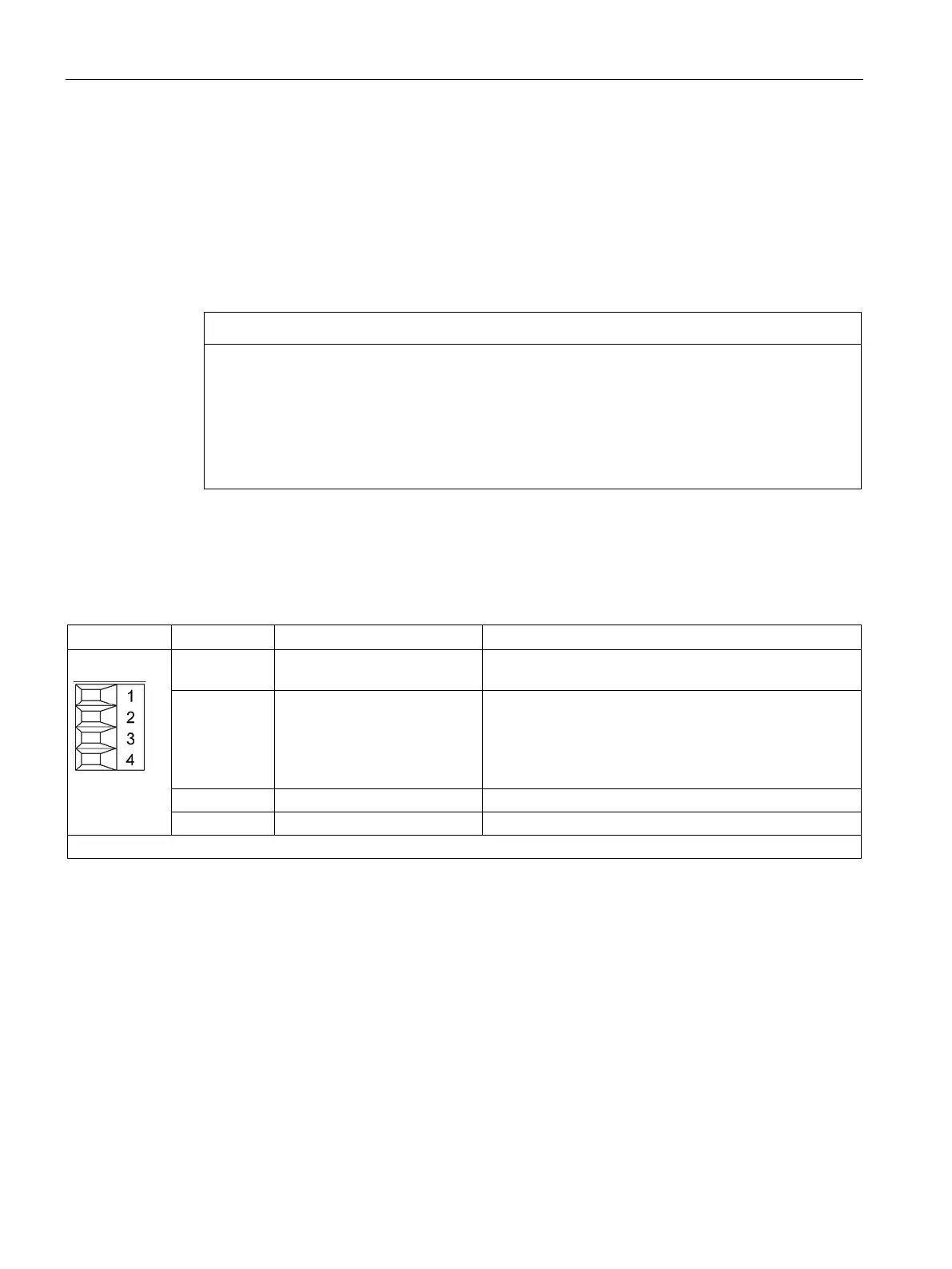
Table 4- 68 X22 digital inputs for Smart Line Modules 5 kW and 10 kW
1 24 V power supply Electronics power supply for controlling digital inputs
2 DI: Disable Regeneration Deactivate regenerative feedback (high active)
No power is supplied back to the network from the DC
link. The regenerative energy of the motors may have to
be reduced using a combination of the Braking Module
Reset faults (negative edge)
Type: Screw terminal 1 (Page 730)

 Loading...


