DC link components
8.6 Control Supply Module CSM
Booksize Power Units
Manual, (GH2), 07/2016, 6SL3097-4AC00-0BP8
533
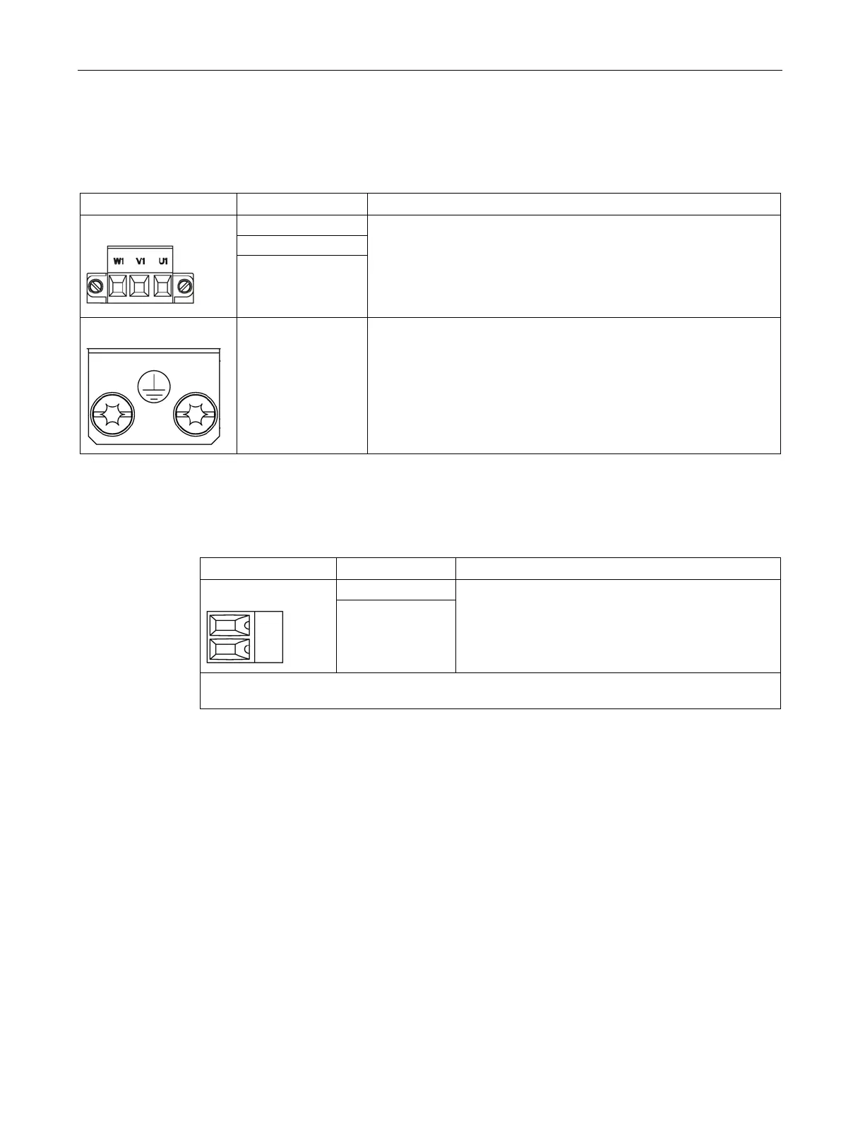
Table 8- 22 X1 line connection
Supply voltage:
3 AC 380 V … 480 V, 50 / 60 Hz
Type: Screw terminal 4 (Page 730)
W1
PE connection M5 screw / 3 Nm at the housing
Table 8- 23 X21 signaling contact
Voltage: 24 V DC
Max. load current: 0.5 A (ohmic load)
2
Type: Screw terminal 1_1 (Page 730)
Max. cross-section that can be connected 1.5 mm
2
The 2-pole terminal connector for the signaling contact is included in the Completion Kit provided.
The signaling contact can be connected with a digital input (DI) on the Control Unit or other
digital interface (PLC, SCADA). In parallel or redundant operation the failure of a Control
Supply Module is indicated in order to initiate a service call, for example.
The signaling contact operates as an isolated NO contact. The contact is closed ("OK") if the
Control Supply Module is operating without fault. For a module output voltage that deviates
from the specification, or an overtemperature condition, then the contact opens ("not OK").
The Control Supply Module is shutdown if an overtemperature condition remains after this
warning.

 Loading...


