Cabinet design and EMC Booksize
12.4 Arrangement of components and equipment
Booksize Power Units
Manual, (GH2), 07/2016, 6SL3097-4AC00-0BP8
677
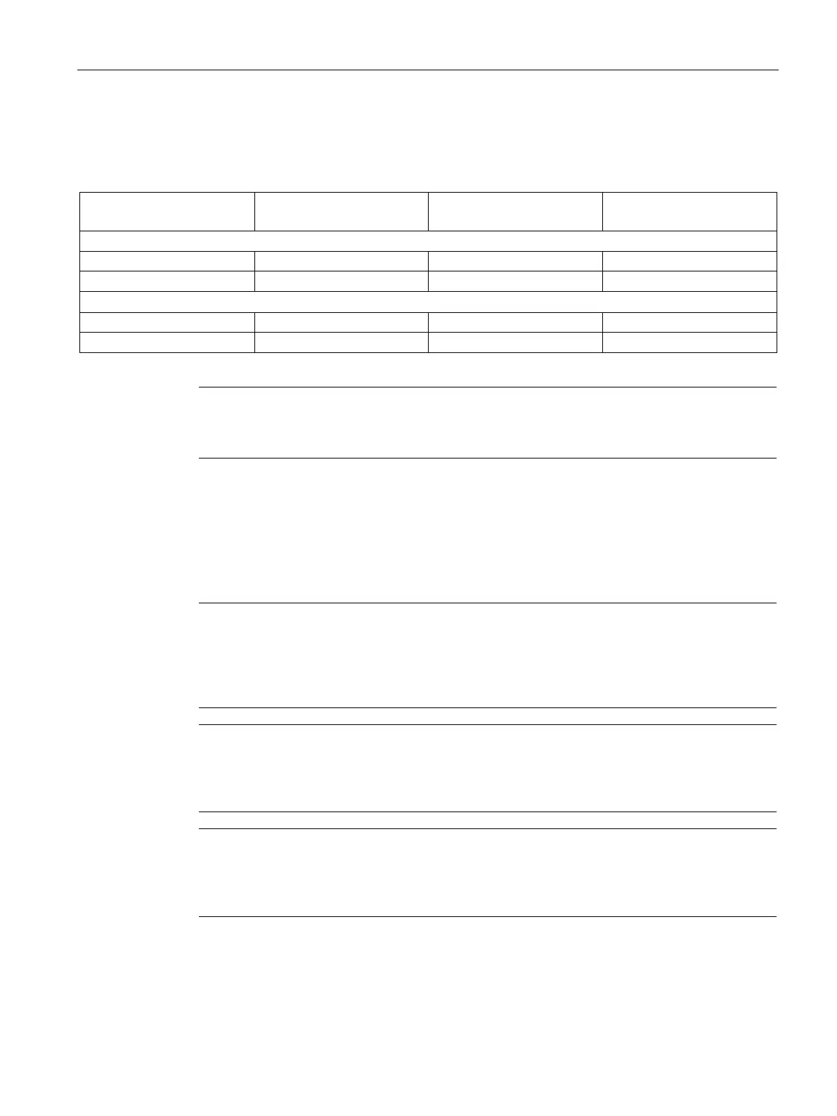
Selecting the DC link rectifier adapter and DC link adapter
Table 12- 2 Overview of the DC link rectifier adapter and DC link adapter
Suitable for module width
Max. connectable cross-
section
Max. current carrying capaci-
ty
DC link rectifier adapter (cable outlet on top)
2
2
DC link adapter (cable outlet on side)
2
6SL3162-2BM10-0AA. 50 mm, 100 mm 95 mm
2
150 A
Note
Using DC link adapters
DC link adapters are o
nly required to configure a multi-tier drive line-up.
Connection versions for the DC link adapter
Depending on the technical requirements and the space available in the control cabinet, for
multi-tier drive line-ups, there are different options when it comes to connecting the DC-link
adapter.
Note
Special feature: Short DC-link screws
Because of the compact construction and the required voltage separations, the left
-hand DC
-
link screws are shorter (16
mm) than the other DC-link screws (20 mm) for modules with 50-
mm installation width.
Note
Special feature: Different number of DC-link screws
Modules with an installation width of 200
mm or larger require two screws per DC-
-hand DC-link connection side in order to carry the higher amperages.
Note
Special feature: Washers during installation of the DC-link adapter
The supplied washers must also be installed on the left
-hand side during the installation of
-link adapter for modules with an installation width of 150 mm or greater.

 Loading...


