Line Modules Booksize
4.7 Basic Line Modules with internal air cooling
Booksize Power Units
Manual, (GH2), 07/2016, 6SL3097-4AC00-0BP8
227
Table 4- 45 Braking resistors with a thermostatic switch for 20 kW and 40 kW Basic Line Modules
6SE7021-6ES87-2DC0 40 2.5 10 15
6SE7028-0ES87-2DC0
1)
8 12.5 50 75
1)
Not suitable for 20 kW Basic Line Module
For detailed technical information on the braking resistors, see the section entitled Braking
resistors (Page 549).
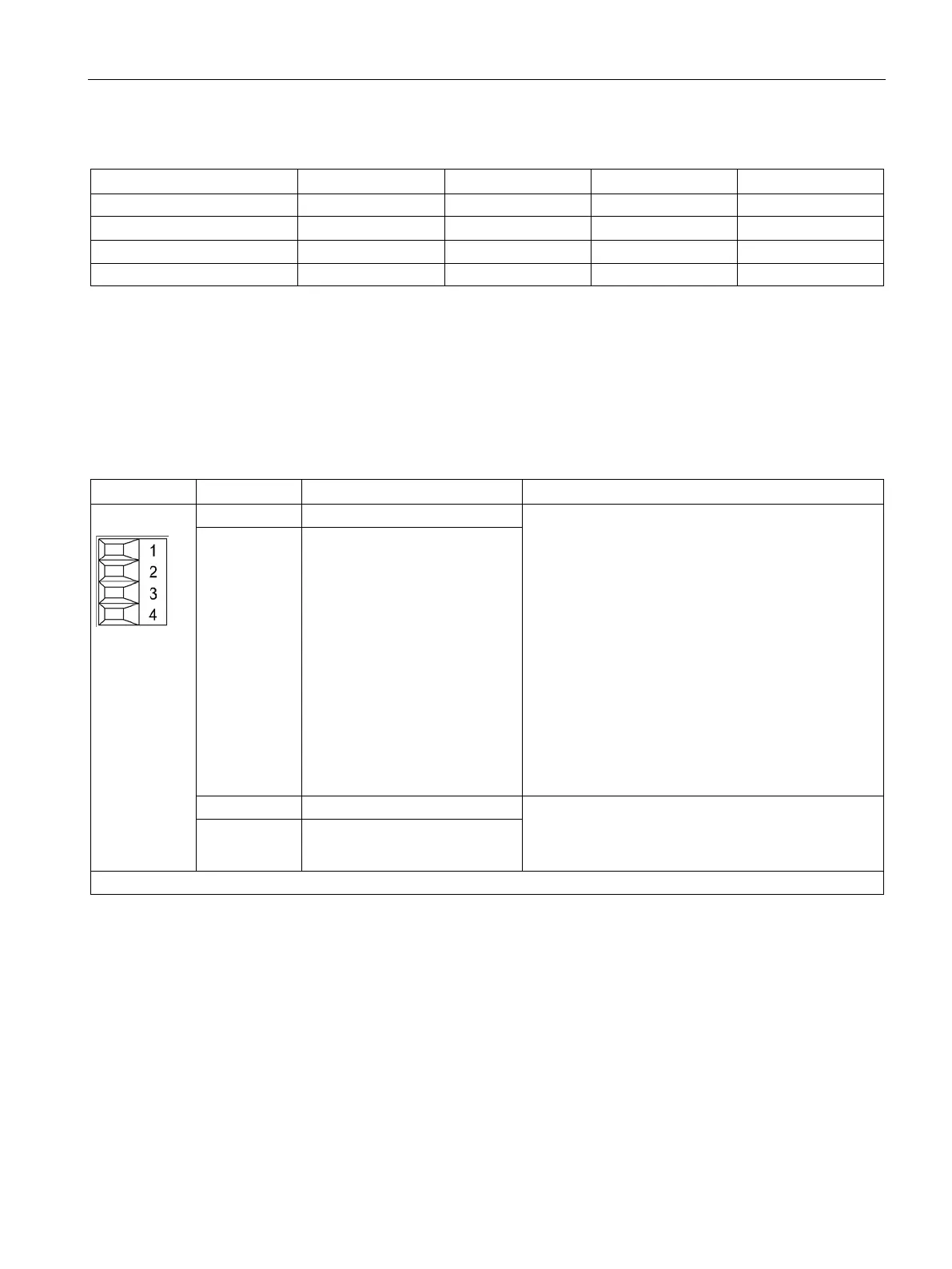
Table 4- 46 X21 EP terminal / temperature sensor
Temperature sensors
1)
: KTY84-1C130
2)
/ PT1000
2)
/
PTC
2)
/ bimetallic switch with NC contact
With the 20 kW and 40 kW Basic Line Modules, the
temperature sensor of the braking resistor (bimetallic
switch with NC contact) is connected to the tempera-
ture input.
of the temperature input:
Temperature at the braking resistor in the operating
range → resistance value ≤ 100 ohms
Overtemperature at the braking resistor → resistance
value > 100 ohms
Fault responses: An alarm is output and the Basic Line
Module is deactivated with a fault after one minute, if
overtemperature is still present at the braking resistor.
If there is no braking resistor, terminals 1 and 2 must
be jumpered to deactivate the overtemperature.
2 - Temp
3 EP +24 V (pulse enable) Voltage: 24 V DC (20.4 ... 28.8 V)
Current consumption, typical: 4 mA at 24 V
Isolated input
4 EP M (Enable Pulses)
Type: Screw terminal 1 (Page 730)
The temperature sensor type and the temperature output can be selected by parameter (see the SINAMICS S120/S150
List Manual).
2)
Temperatures are detected but not evaluated in the Basic Line Module.

 Loading...


