Motor-side power components
10.2 Voltage Protection Module VPM
Booksize Power Units
Manual, (GH2), 07/2016, 6SL3097-4AC00-0BP8
587
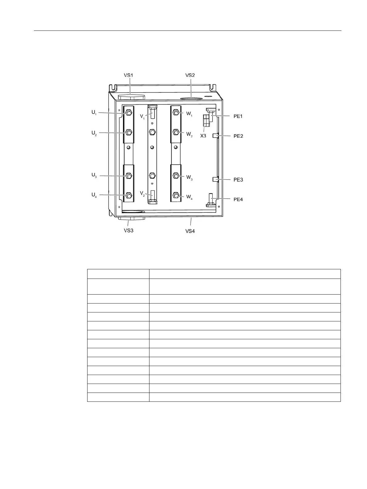
Connecting power cables (using the VPM 200 Dynamik as an example)
Figure 10-16 Connection points of the Voltage Protection Module VPM200 Dynamic
Table 10- 13 Short designations
VS1, VS2 Cable screwed joint 1 or 2 in the housing entry of the VPM, towards Motor
Cable screwed joint 3 or 4 in the housing entry of the VPM, towards motor
Cable 1 or 2 to the Motor Module
Cable 3 or 4 to the motor
Connection bolts on busbar U
3
4
Connection bolts on busbar U
Connection bolts on busbar V
1
2
Connection bolts on busbar W
Connection bolts on busbar W
1
2
3
4
Connection bolts on busbar PE

 Loading...


