Line Modules Booksize
4.9 Smart Line Modules with internal air cooling
Booksize Power Units
Manual, (GH2), 07/2016, 6SL3097-4AC00-0BP8
269
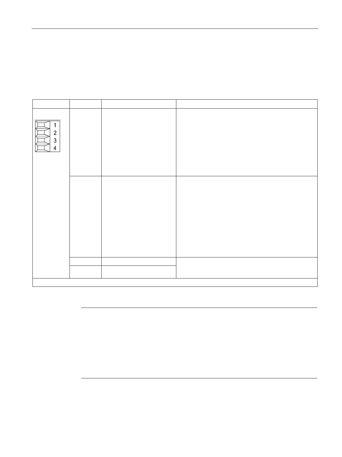
X21 EP terminals
Smart Line Modules 5 kW and 10 kW
Table 4- 66 X21 EP terminal for Smart Line Modules 5 kW and 10 kW
1 DO: Ready Feedback signal: Smart Line Module ready
The signal switches to high level when the following condi-
tions have been met:
• Electronics power supply (X24) OK
• DC link is precharged
• Pulses enabled (X21.3/4)
• No overtemperature
• No overcurrent
2 DO: Prewarning
DO: Prewarning
High = no prewarning
Low = prewarning
• Overtemperature warning threshold/I
2
t
5 kW
prewarning: 64 °C, overtemperature threshold: 69 °C
10 kW
prewarning: 68 °C, overtemperature threshold: 73 °C
• No regenerative feedback capability due to a line fault
[only monitored when feedback is activated (see termi-
nal X22.2)]
Voltage: 24 V DC (20.4 ... 28.8 V)
Current consumption, typical: 4 mA at 24 V
4 EP M (Enable Pulses)
Type: Screw terminal 1 (Page 730)
Terminals X21.1 and X21.2
Note
Wiring to a digital input of the Control Unit
Output terminal X21.1 must be wired to a digital input on the CU. The drives supplied with
power from the Smart Line Module have to use this signal as a ready signal. This ensures
that a pulse enable can only be issued for the drives (motor or generator operation) when the
infeed is ready.
If interconnection with a digital input on the CU is not possible, the signal must be evaluated
by a higher
-level control system instead. It is not permissible that the control system sets the
to ready until the infeed "Ready" signal is present.

 Loading...


