Motor Modules Booksize
6.5 Motor Modules Liquid Cooled
Booksize Power Units
446 Manual, (GH2), 07/2016, 6SL3097-4AC00-0BP8
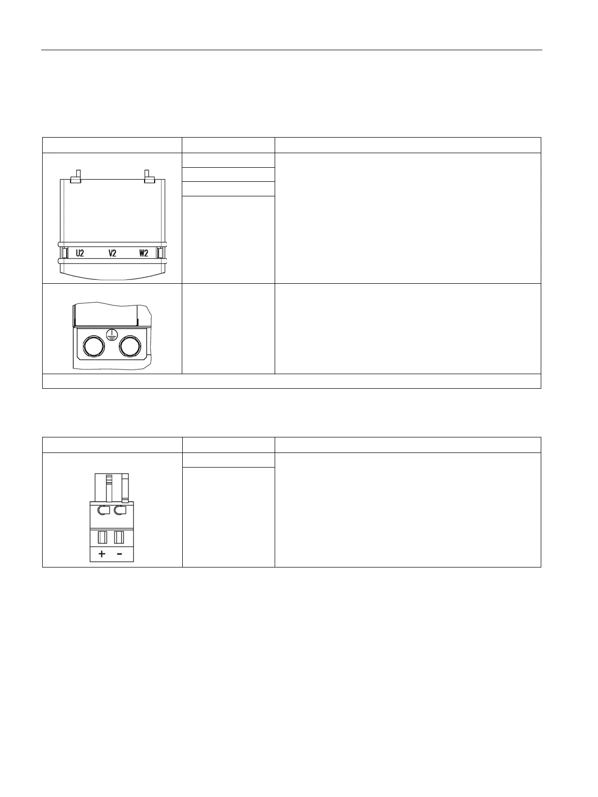
Motor and brake connection
Table 6- 47 X1 Motor connection
Threaded bolts M8 / 13 Nm
1)
- (BR-)
PE connection Threaded hole M8 / 13 Nm
1)
1)
For ring cable lugs without insulation (Page 732)
Table 6- 48 X11 brake connector
Voltage 24 V DC
Max. Load current 2 A
Minimum load current 0.1 A
Type: Spring-loaded terminal 2 (Page 730)
The brake connector is part of the prefabricated cable.
- (BR-)
The circuit for protecting the brake against overvoltage is integrated in the Motor Module and does not need to be installed
externally.

 Loading...


