DC link components
8.4 Braking units for 100 kW Basic Line Modules
Booksize Power Units
Manual, (GH2), 07/2016, 6SL3097-4AC00-0BP8
519
Note
After the DC link voltage is applied, fault output
-X38/5 is "low" for approx. 2 seconds (self-
test), i.e. in the "fault" state. The Control Unit must suppress this state when the system is
switched on.
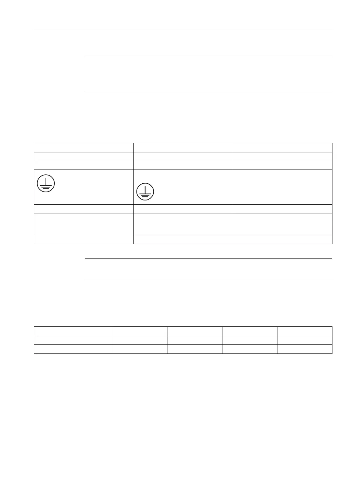
X6 braking resistor connection
Table 8- 19 X6: Connection for the braking resistor
G/R+ external braking resistor
H/R external braking resistor
Protective conductor
Busbar PE
16
M6 bolts at bottom of housing
Connection via Cable lug without insulation (Page 732)
With shrink-on sleeve
Cable is connected using the supplied M8 x 25 screws
Note
The cable length between the braking unit and the braking resistor is limited to 15
m.
The following braking resistors are suitable for connecting to the MASTERDRIVES braking
unit:
Table 8- 20 Braking resistors for MASTERDRIVES braking unit
6SE7032-7ES87-2DC0 42.5 170 255 2.35

 Loading...


