Cooling circuit and coolant properties
13.1 Cooling circuit requirements
Booksize Power Units
Manual, (GH2), 07/2016, 6SL3097-4AC00-0BP8
773
Cooling circuit configuration
The liquid-cooled power units are designed to be connected in parallel to the cooling circuit.
The pressure drop in the joint supply and return lines is to be kept at negligible levels by
choosing a sufficiently large pipe diameter. The intake has differential pressure p with
respect to the return. This pressure is usually generated by a pump.
The pressure of a pump depends on the flow rate. Therefore, depending on the number of
connected components, a different pressure is obtained. At the minimum differential
pressure p1 (measured between the supply and return lines of the individual component),
the volume of coolant required to enable the component to achieve its rated power or rated
current is to flow through each component. At the maximum differential pressure p2
(measured between the supply and return lines of the individual component), the volumetric
flow must not result in damage to the component, for example, by means of cavitation. If
necessary, pressure reducing valves such as baffle plates will have to be installed in the
piping; these must be easy to access, clean, and/or replace.
When the pump is switched off, static pressure occurs in the system. The static pressure can
be influenced by the primary pressure of the membrane expansion tank and should be at
least 30 kPa on the pump's suction side. If the static pressure is too low, there is the risk that
the pump will be damaged by cavitation when operational. Otherwise, minimum pressure
values different than those specified by the pump manufacturer must be observed. When
components are installed at different heights, the geodesic pressure caused by the height
difference must be taken into account (1 m height difference corresponds to 10 kPa).
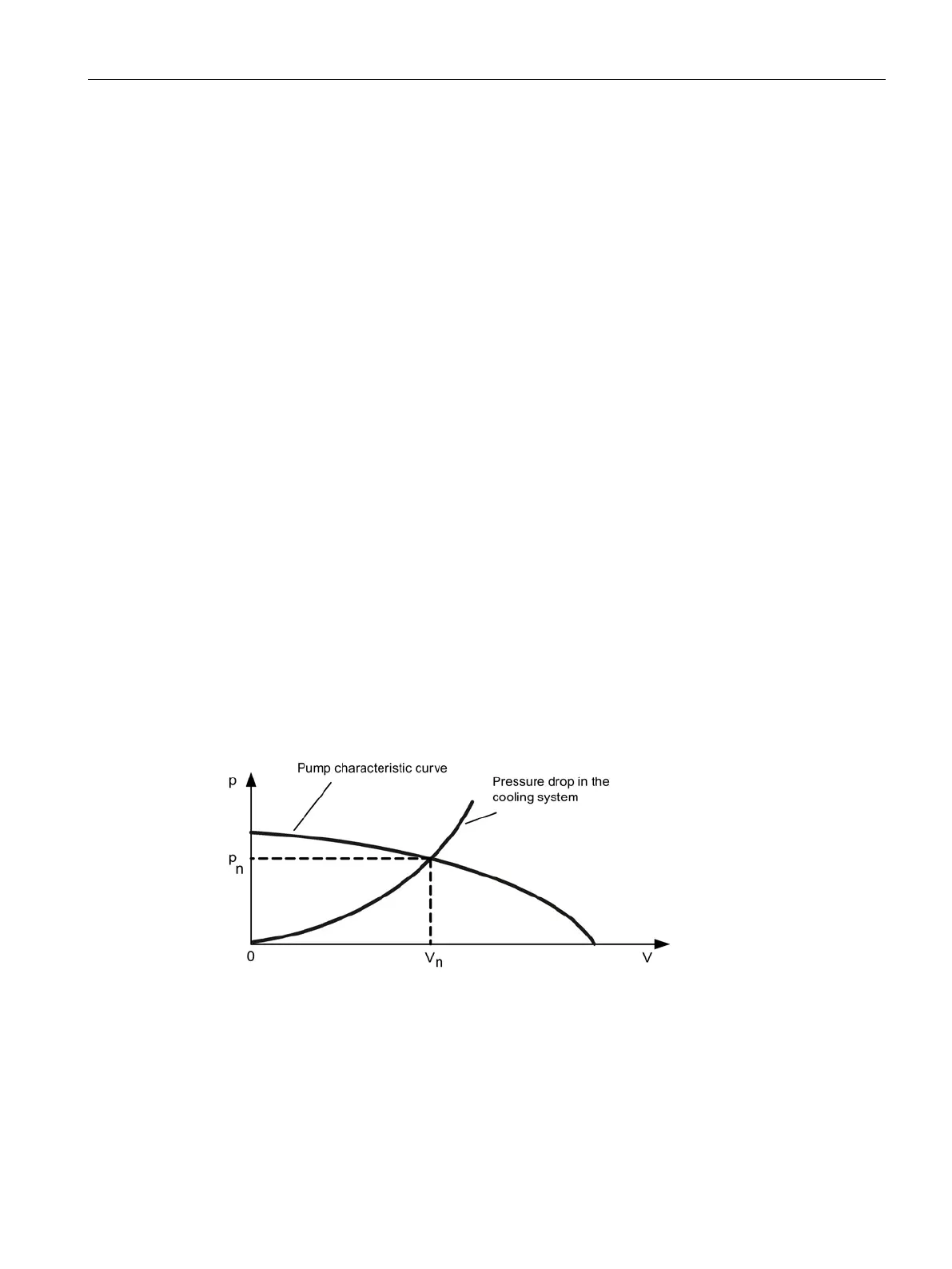
When the pump is switched on, a (location-dependent) flow pressure is present in the
cooling circuit, which must be determined from the pump characteristic curve and the
volume-flow-dependent pressure drop. The pressure drop in the filter and, if applicable, an
additional pressure drop in the connection pipes must be added to the pressure drop of the
liquid-cooled power units (70 kPa for H
2
O). Up to 50 kPa must be added for the pressure
drop in a (contaminated) filter and in connection pipes. The intersection of the pump
characteristic curve and the pressure drop of the whole cooling system yields the volumetric
flow V
rated
of the coolant at this operating point.
Figure 13-1 Pump characteristic curve
Permissible system pressure

 Loading...


