Cabinet design and EMC Booksize
12.5 Electrical connection
Booksize Power Units
692 Manual, (GH2), 07/2016, 6SL3097-4AC00-0BP8
Danger to life through electric shock if the cutout in the protective cover has been broken
out
Live components are open and accessible if the 24 V terminal adapter or the DC link infeed
adapter are removed. Touching live components can result in death or severe injury.
• Replace the protective cover with the broken out cutouts by a new protective cover.
Note
The 24 V terminal adapter should always be installed to the left of the component located at
the far
left, because if it is positioned anywhere else there may not be enough space for the
-in jumpers.
If necessary, the 24 V terminal adapter can also be located at the right for 50
mm and
mm modules.
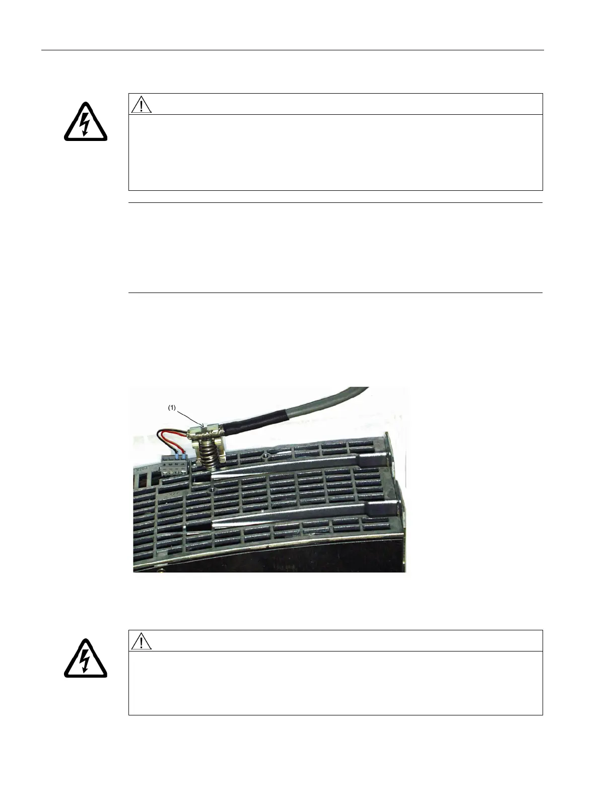
Shield connection for terminals X21/X22 on the Motor Module
The diagram below shows a typical shield connection terminal for the shield support of the
cables to terminal X21.
Shield connection clamp: Weidmüller, type KLBÜ 3-8 SC
Figure 12-20 Shield connection terminal for the shield support
Danger to life due to electric shock when using screws with the incorrect length
Excessively long screws can come into contact with live parts and can therefore result in
death or serious injury.
• Only use screws with a permissible insertion depth of 4 - 6 mm.