Motor Modules Booksize Compact
7.3 Interface description
Booksize Power Units
Manual, (GH2), 07/2016, 6SL3097-4AC00-0BP8
467
Note
The total length of the power cables (motor feeder cables and DC link cables) must not
exceed the values listed in Chapter
Combination options, Line Modules with line reactors
(Page 135).
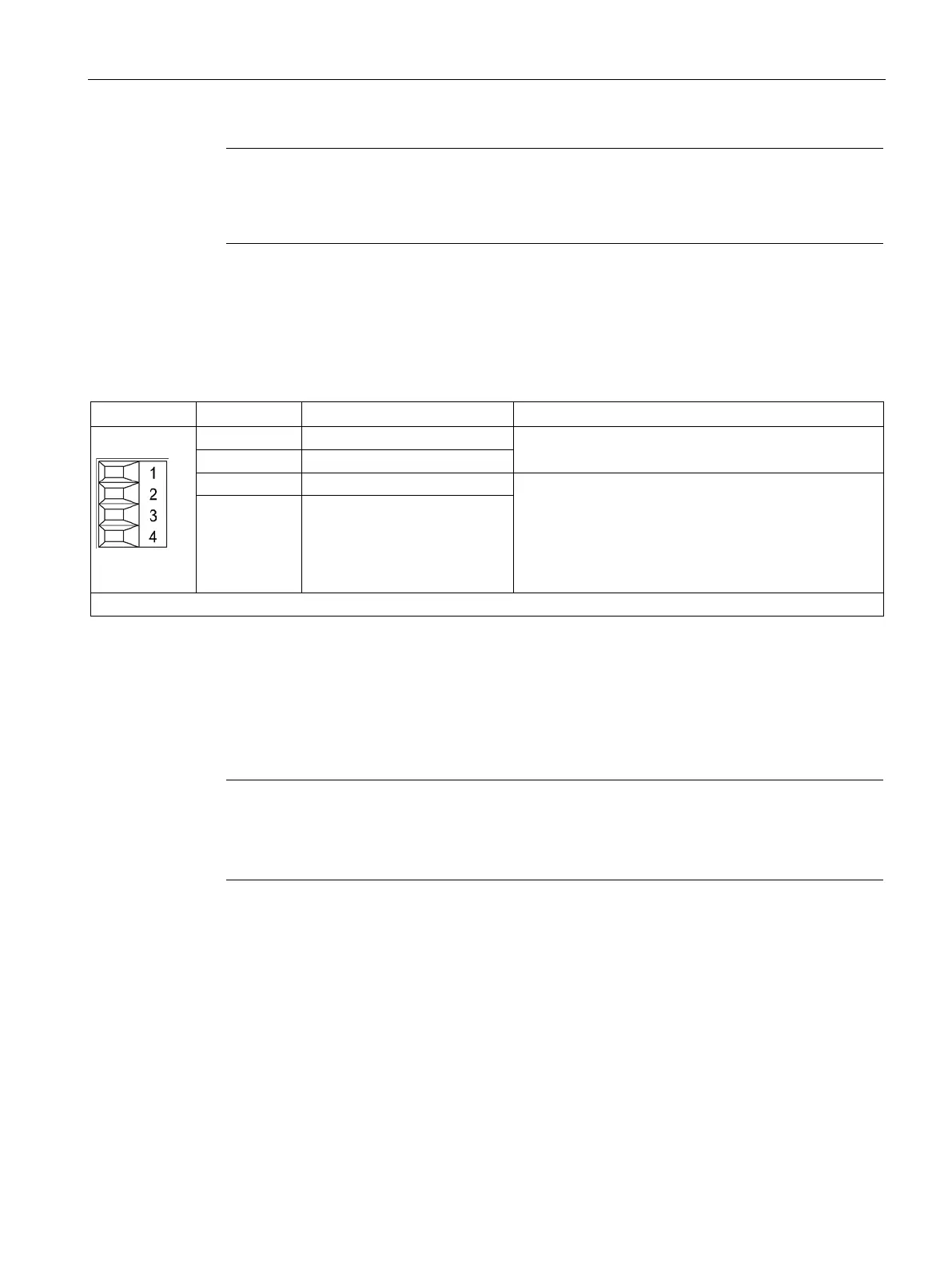
X21/X22 EP terminals/temperature sensor
Table 7- 3 X21/X22 EP terminals / temperature sensor
Temperature sensors: KTY84–1C130 / PT1000 / PTC /
bimetallic switch with NC contact
Supply voltage: 24 V DC (20.4 ... 28.8 V)
Current consumption, typical: 4 mA at 24 V
Isolated input
The pulse inhibit function is only available when the
"Safety Integrated Basic Functions via onboard termi-
nals" software is enabled.
4 EP M1 (enable pulses)
Type: Screw terminal 1 (Page 730)
Parameters are used to set the filter times to debounce terminals X21.3 and X21.4, as well
as X22.3 and X22.4 (see the SINAMICS S120/S150 List Manual). Additional parameter
settings are also required in order to prevent discrepancy errors when performing bit pattern
tests (light/dark tests). For comprehensive information, see the SINAMICS S120 Safety
Integrated Function Manual, Section "Controlling the safety functions".
Note
Function of the EP terminals
The function of the EP terminals for pulse inhibit is only available if the "Safety Integrated
Basic Functions via onboard terminals" software is enabled.

 Loading...


