Line Modules Booksize
4.3 Active Line Modules with internal air cooling
Booksize Power Units
Manual, (GH2), 07/2016, 6SL3097-4AC00-0BP8
157
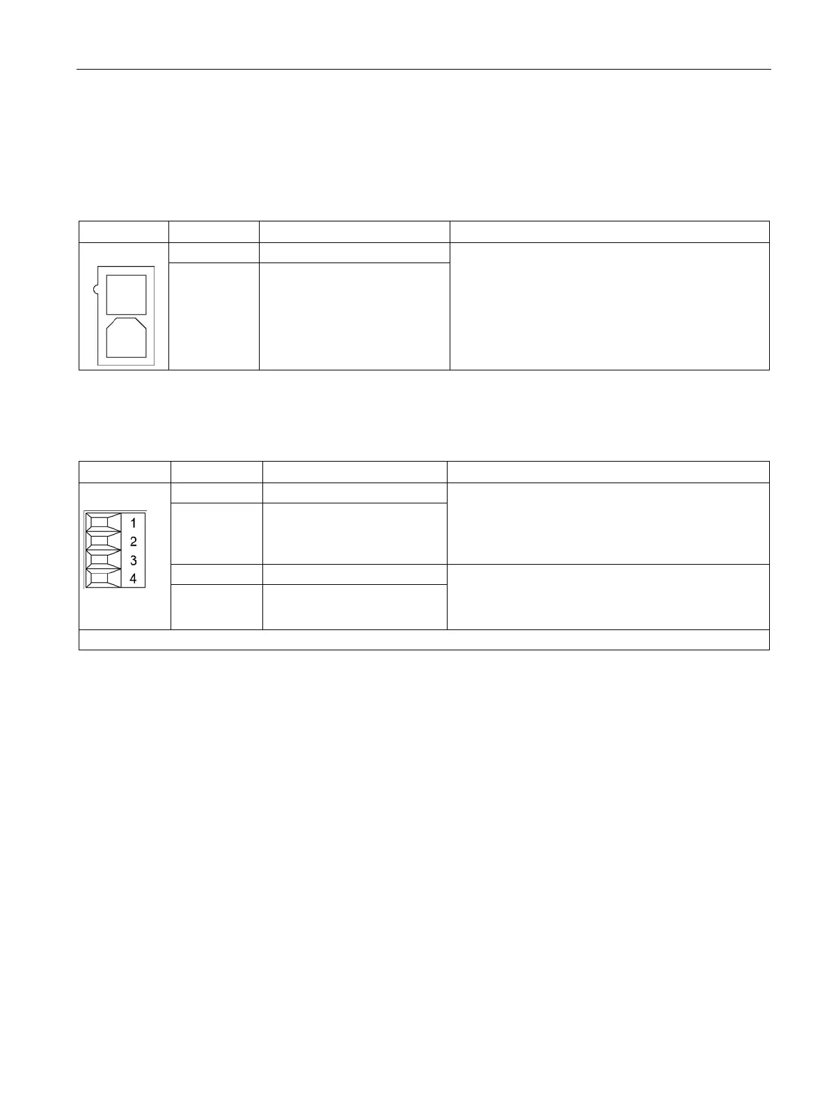
Active Line Modules 80 kW and 120 kW are equipped with an interface for connecting the
sub-chassis fan. The interface is located on the underside of the Line Module.
Table 4- 3 X12 fan connection
Voltage 48 V DC for the supplied fan
2 Fan connection -
Table 4- 4 X21 EP terminal / temperature sensor
Temperature sensors
1)
: KTY84–1C130
2)
/ PT1000
2)
/
PTC
2)
/bimetallic switch with NC contact
If an Active Interface Module is used, the temperature
input must be connected to the Active Interface Module
sensor (bimetallic switch with NC contact).
2 - Temp
Voltage: 24 V DC (20.4 ... 28.8 V)
Current consumption, typical: 4 mA at 24 V
Isolated input
4 EP M (Enable Pulses)
Type: Screw terminal 1 (Page 730)
The temperat
ure sensor type and the temperature output can be selected by parameter (see the SINAMICS S120/S150
List Manual).
2)
Temperatures are detected but not evaluated in the Active Line Module.
Terminals X21.1 and X21.2
When using an Active Interface Module, its temperature output must be connected at
terminals X21.1 and X21.2.
Terminals X21.3 and X21.4
For operation, the 24 V DC voltage must be connected to terminal X21.3 and ground to
terminal X21.4.
Pulse cancellation is activated if the power supply is disconnected. As a consequence,
regenerative feedback is deactivated and the bypass relay drops out. If the Line Module is
not disconnected from the line supply when the EP terminal is de-energized, for example,
because a line contactor is not installed, then the DC link remains charged.

 Loading...


