DC link components
8.2 Braking Module Booksize
Booksize Power Units
492 Manual, (GH2), 07/2016, 6SL3097-4AC00-0BP8
X21 digital inputs/outputs
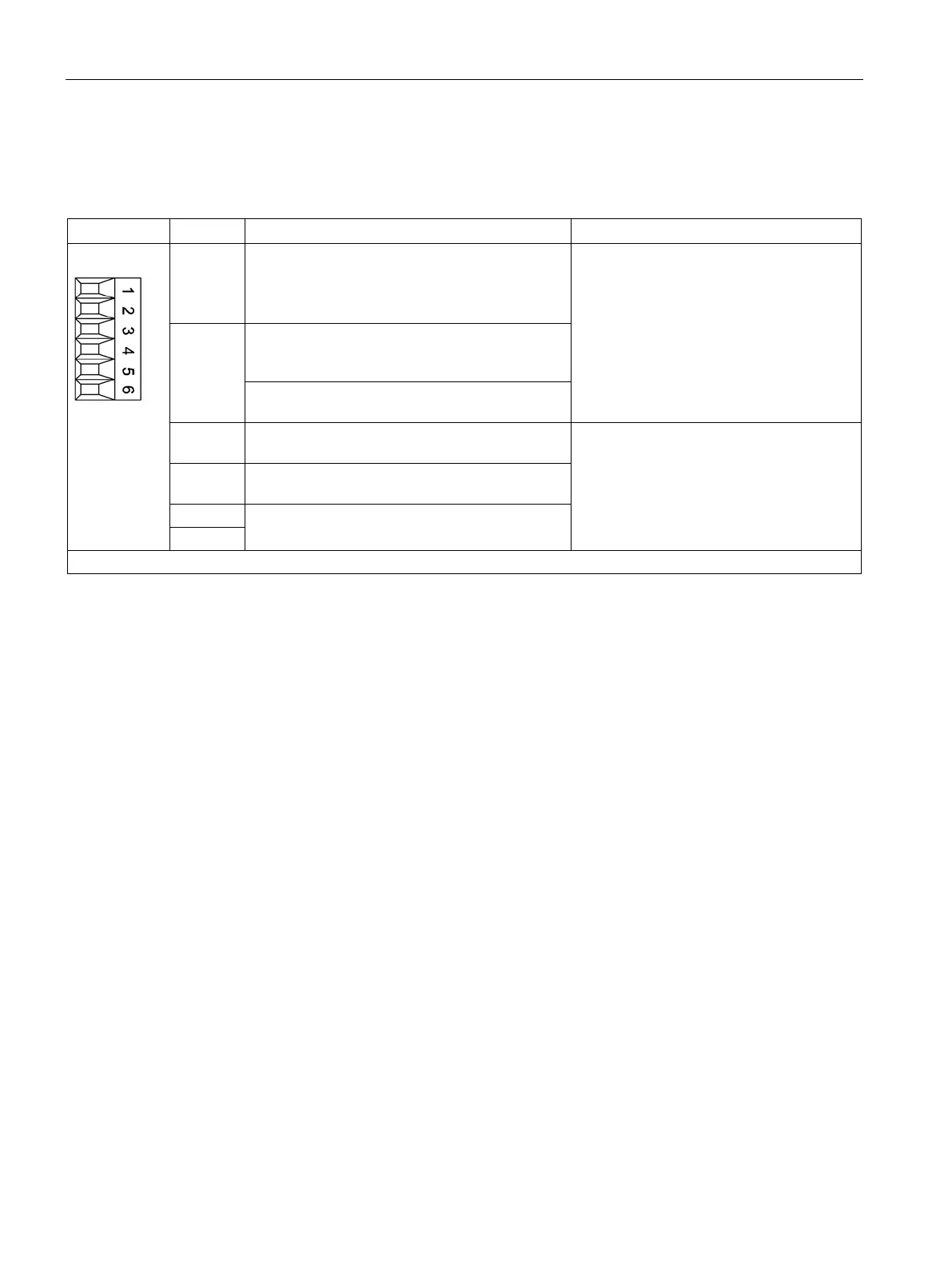
Table 8- 3 X21 digital inputs/outputs
1 DI low: Enable Braking Module
DI high: inhibit/acknowledge
Edge change, high → low: fault acknowledge-
Voltage: -3 … +30 V
Typical current drain:
10 mA at 24 V DC
Level (incl. ripple)
High level: 15 … 30 V
Low level: -3 … +5 V
2 DI low: braking resistor, not controlled manually
DI high: Braking resistor controlled manually
2)
If X21.1 and X21.2 are activated simultaneously,
the Braking Module inhibit has priority.
3 DO high: no prewarning
DO low: Prewarning, disconnection imminent
Max. load current per output: 100 mA
Continuously short-circuit proof
Voltage: 24 V DC
4 DO high: ready for operation, no fault
Ground
Type: Screw terminal 1 (Page 730)
DI: digital input; DO: digital output; M: Electronics ground
The "fast discharge function" is used for discharging the capacitors in the DC link after the line supply has been inter-
rupted. It may only be used a maximum of once or twice per week.
Terminal X21.1 - inhibit/acknowledge
Applying a high signal to terminal X21.1 inhibits the Braking Module. Fault messages that
are available are acknowledged with a falling edge.
Terminal X21.3 - prewarning
When a prewarning is sent, disconnection of the braking module is imminent. This may be
due to the following causes:
● The temperature of the Braking Module is 80 % of the maximum value.
● 80 % of the maximum switch on duration of the braking resistor has been reached (I
2
t
monitoring).
● 80 % of the maximum braking energy of the braking resistor has been reached.
● An incorrect braking resistor is connected (only braking resistors approved by Siemens
for this component are automatically identified).
The fault can have the following causes:
● Electronics power supply is missing or outside permissible tolerance range
● Enable missing (input terminal)
● Overtemperature

 Loading...


