Motor-side power components
10.2 Voltage Protection Module VPM
Booksize Power Units
578 Manual, (GH2), 07/2016, 6SL3097-4AC00-0BP8
Connection bars U, V, W, PE
The cables to the Motor Module and motor are routed through the cable entry of the Voltage
Protection Module and attached to the connection bars inside the unit.
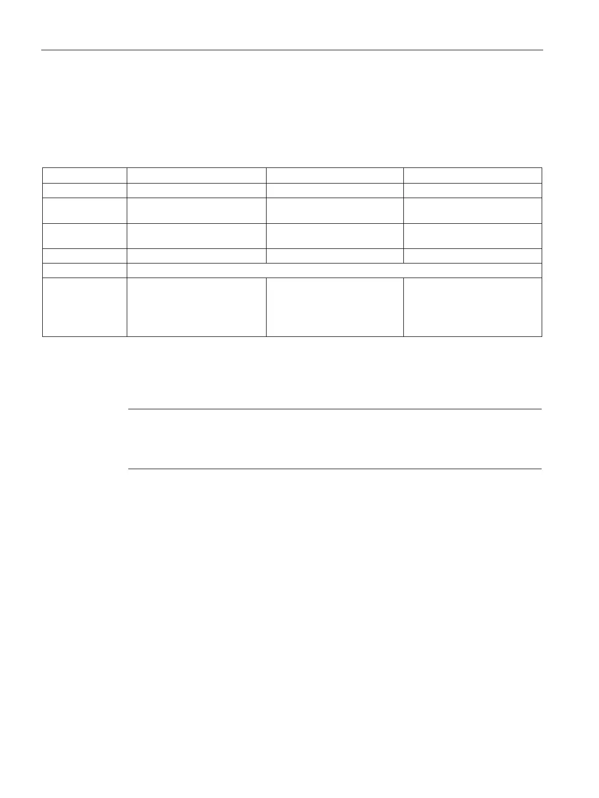
Table 10- 12 Connections U, V, W, and PE
1)
1)
2)
Cable lug Crimp-type cable lug M6 Crimp-type cable lug M8 Tubular cable lug M8,
90° angled
Cable cross-
≤ 50 mm
2
≤ 50 mm
2
≤ 50 mm
2
For cables with max. 40 mm ∅
Gland
3)
2 x M50
e.g. from the Pflitsch company,
Art. desig.: UNI DICHT EMV
250584117
4 x M50
e.g. from the Pflitsch company,
Art. desig.: UNI DICHT EMV
250584117
4 x M50
e.g. from the Pflitsch company,
Art. desig.: UNI DICHT EMV
250584117
There are 2 connection points for each phase and for PE.
There are 4 connection points for each of the phases U, W, and PE and 2 connection points for phase V.
3)
The glands must be separately ordered.
Note
Cable lengths with cross
-sections of > 50 mm
2
between the Motor Module and the Voltage
Protection Module or between the Voltage Protection Module and the motor are
implemented using two cables connected in parallel.

 Loading...


