Cabinet design and EMC Booksize
12.11 Notes on electrical cabinet cooling
Booksize Power Units
Manual, (GH2), 07/2016, 6SL3097-4AC00-0BP8
755
Measures for remaining within temperature limits
● One or more fans should be installed.
● If necessary, the drive line-up can be operated with derating.
Dimensioning Climate Control Equipment
Cabinet manufacturers provide calculation programs for selecting climate control equipment.
It is always necessary to know the power loss of the components and equipment installed in
the cabinet.
The physical relationship is shown in the following example.
q = Q - k x A x ΔT
Formula to calculate the power loss
q = thermal power that has to be dissipated through a cooling unit [W]
Q = power loss [W]
∆T = temperature difference between the room and cabinet interior [K]
k = thermal resistance coefficient [W / (m
2
* K)]
(example: sheet steel, painted: k = 5.5 W / (m
2
* K))
A = free-standing cabinet surface area [m
2
]
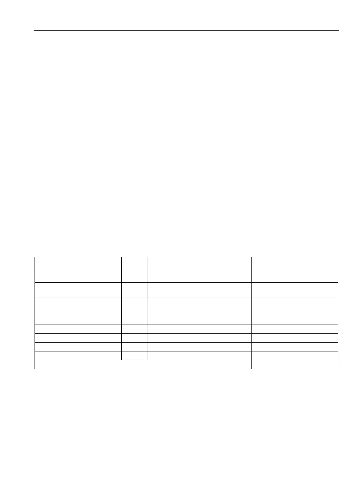
Table 12- 33 Example, calculating the power loss of a drive configuration
Total power loss [W]
(including electronic losses)
Basic Line Filter for AIM / ALM 36
1 26 26
Active Line Module 36 kW 1 666 666
Assumption:
Free-standing cabinet surface area A = 5 m
2
Temperature difference between the room and cabinet interior ∆T = 10 K
q = 2469.4 W - 5.5 W / (m
2
K) * 5 m
2
* 10 K = 2194.4 W

 Loading...


