Cabinet design and EMC Booksize
12.5 Electrical connection
Booksize Power Units
Manual, (GH2), 07/2016, 6SL3097-4AC00-0BP8
689
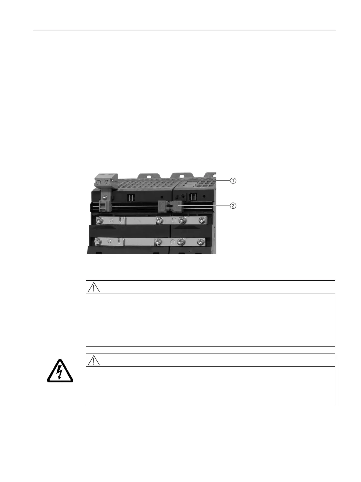
Connection of the 24 V busbars
Connection of the 24 V busbars
The 24 V busbars of the components are connected using the 24 V connectors provided in
the accessories pack. A 24 V connector must be plugged onto the 24 V busbars between the
Line Module, Motor Module and DC link component. The 24 V connectors must be attached
before the drive line-up is commissioned!
1. Place the 24 V connectors on to the 24 V busbars.
2. Press the 24 V connectors down until they click into place.
3. If required, mount the 24 V terminal adapter to supply the 24 VDC.
Mounted 24 V terminal adapter (Torx T10, tightening torque 0.5 Nm)
Fire hazard for 24 V connectors and unconnected DC link busbars
For drive lineups in series, whose DC link busbars are not connected with one another, it is
not permissible to insert 24 V connectors between these drive lineups. Otherwise the 24 V
connectors can burn and cause severe injury or death as result of fire or smoke.
• If the DC link busbars of the components are not connected, each component must be
supplied with 24 V separately via a 24 V terminal adapter.
Danger to life due to electric shock when connecting and disconnecting 24 V connections in
operation
When opening plug connections in operation, arcs can result in severe injury or death.
• Only withdraw or insert the 24 V connectors in a no-voltage state.