ENGINE 3-63
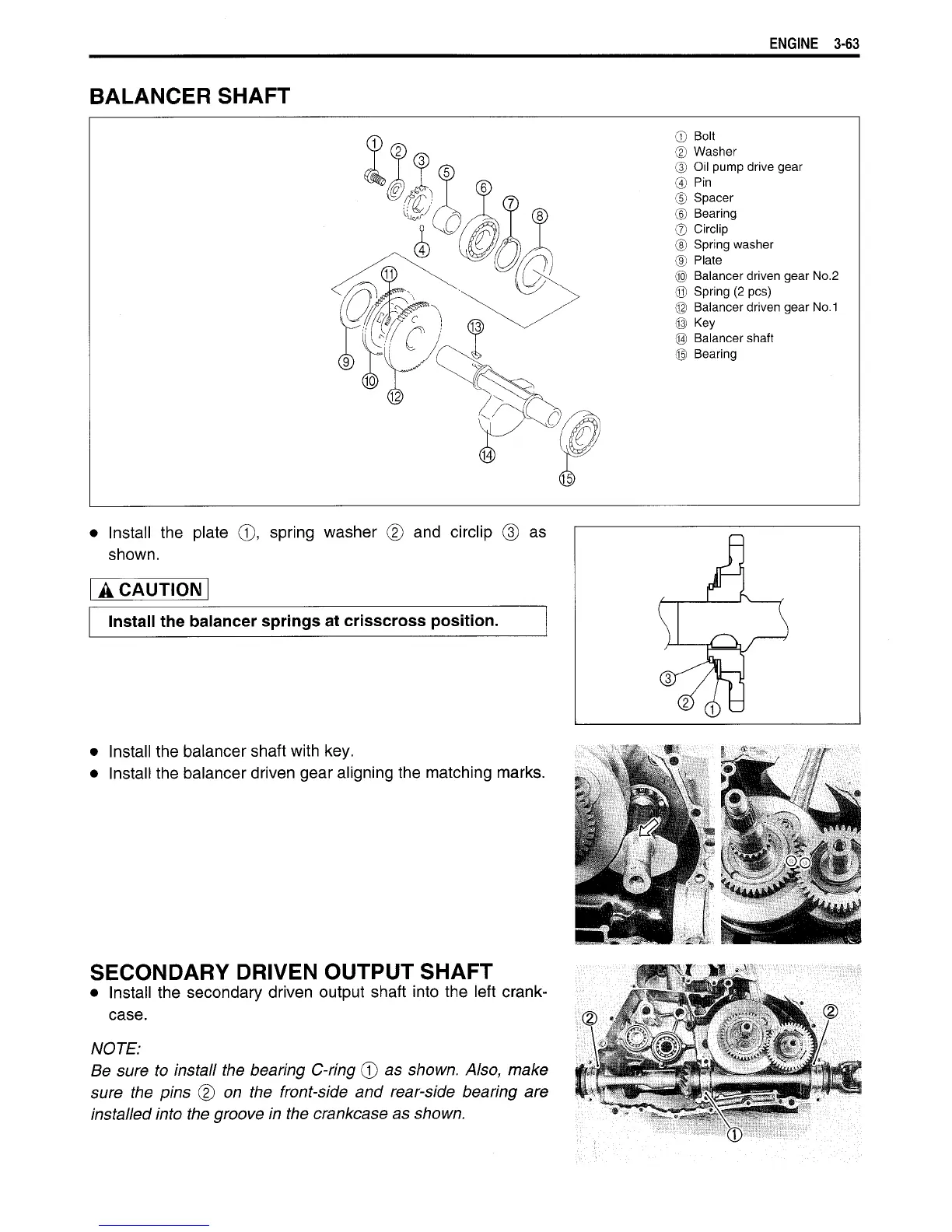
BALANCER
SHAFT
©
Bolt
©
Washer
©
Oil
pump
drive gear
® Pin
©
Spacer
©
Bearing
®
Circlip
®
Spring washer
®
Plate
®
Balancer driven gear No.2
®
Spring
(2
pes)
©
Balancer driven gear No.1
® Key
®
Balancer shaft
©
Bearing
Install
the
plate
©,
spring washer
® and
circlip
shown.
as
A CAUTION
Install the balancer springs at
crisscross
position.
•
Install the balancer shaft with key.
•
Install the balancer driven gear aligning the matching marks.
SECONDARY DRIVEN OUTPUT SHAFT
•
Install the secondary driven output shaft into the left crank-
case.
NOTE:
Be
sure to install the bearing C-ring © as shown. Also, make
sure
the pins © on the front-side and rear-side bearing are
installed
into
the groove in the crankcase as shown.

 Loading...


