8-22
ELECTRICAL
SYSTEM
•
Repeat
the
above
procedure
a
few times and
measure
the
highest pickup coil and power source coil peak voltage.
Tester
knob indication: Voltage (~)
WM Pickup coil peak voltage:
More
than 0.5 V
Power source coil peak voltage:
More
than 0.7 V
PICKUP
COIL AND POWER
SOURCE
COIL
RESISTANCE
•
Remove
the
left
front fender side cover.
(dT
3
7-5)
•
Disconnect the generator coupler
©.
Measure
the resistance between the lead wires using the multi
circuit
tester.
If
the resistance
is
not within the specified value,
the
pickup coil and power source coil must be replaced.
09900-25008:
Multi
circuit tester set
@j Tester knob indication:
Resistance
(12)
EBKJ
Pickup coil resistance:
170-250
Q (Blue-Green)
Power source coil resistance:
0.05-0.5
Q (Yellow-White)
BACK-UP
LIGHT
RELAY
(For E-17)
•
Remove
the back-up light relay
©.
(2):
Rear
box
Ckeck that no continuity exists between the terminals
(D
and
If
continuity
is
found, replace the relay.
IT55L)
09900-25008:
Multi-circuit tester
H
' Tester knob indication: Continuity test (•»))
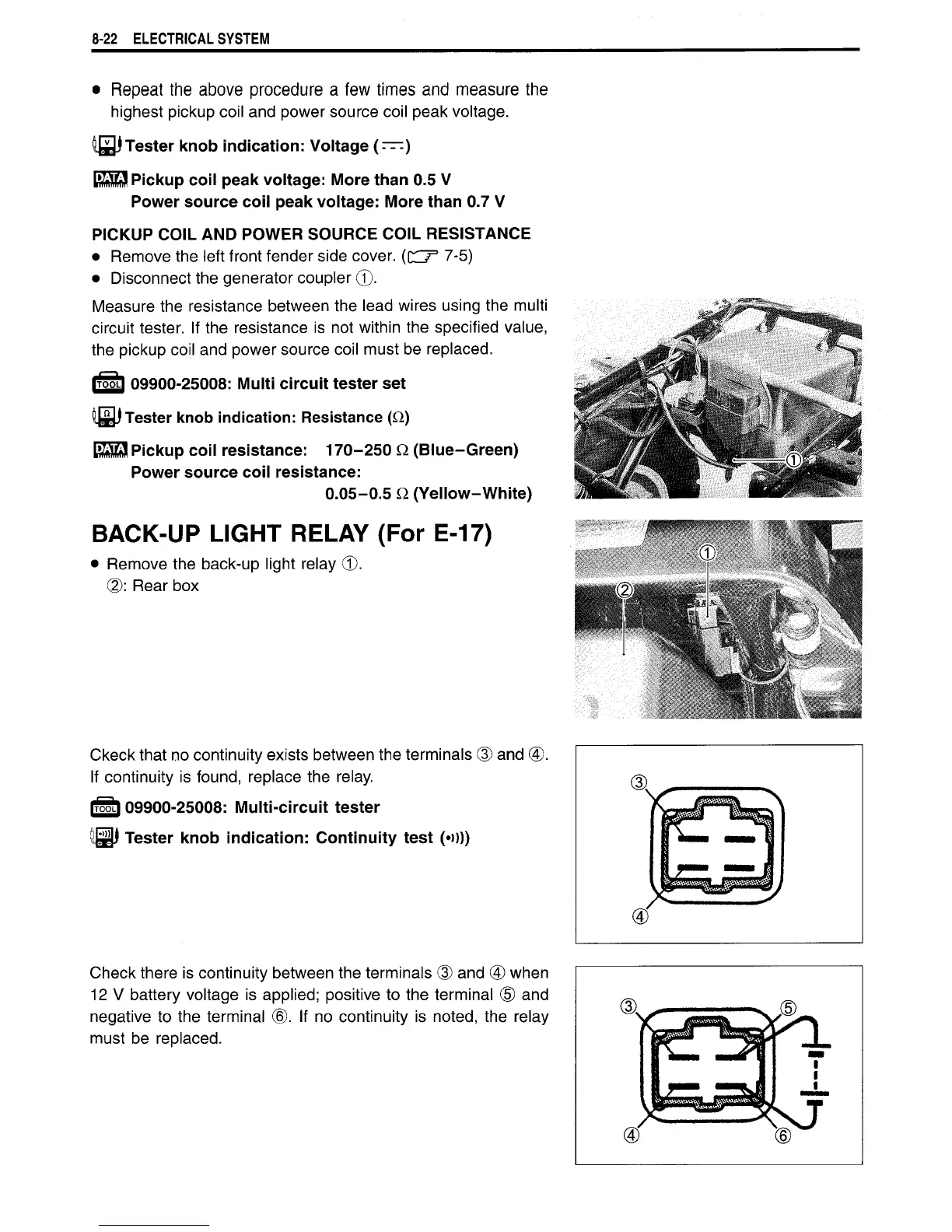
Check
there is continuity between the terminals (3) and (4) when
12
V
battery voltage
is
applied; positive
to
the terminal
(5) and
negative
to
the terminal
(6). If no
continuity
is
noted, the relay
must
be
replaced.

 Loading...


