ELECTRICAL
SYSTEM
8-11
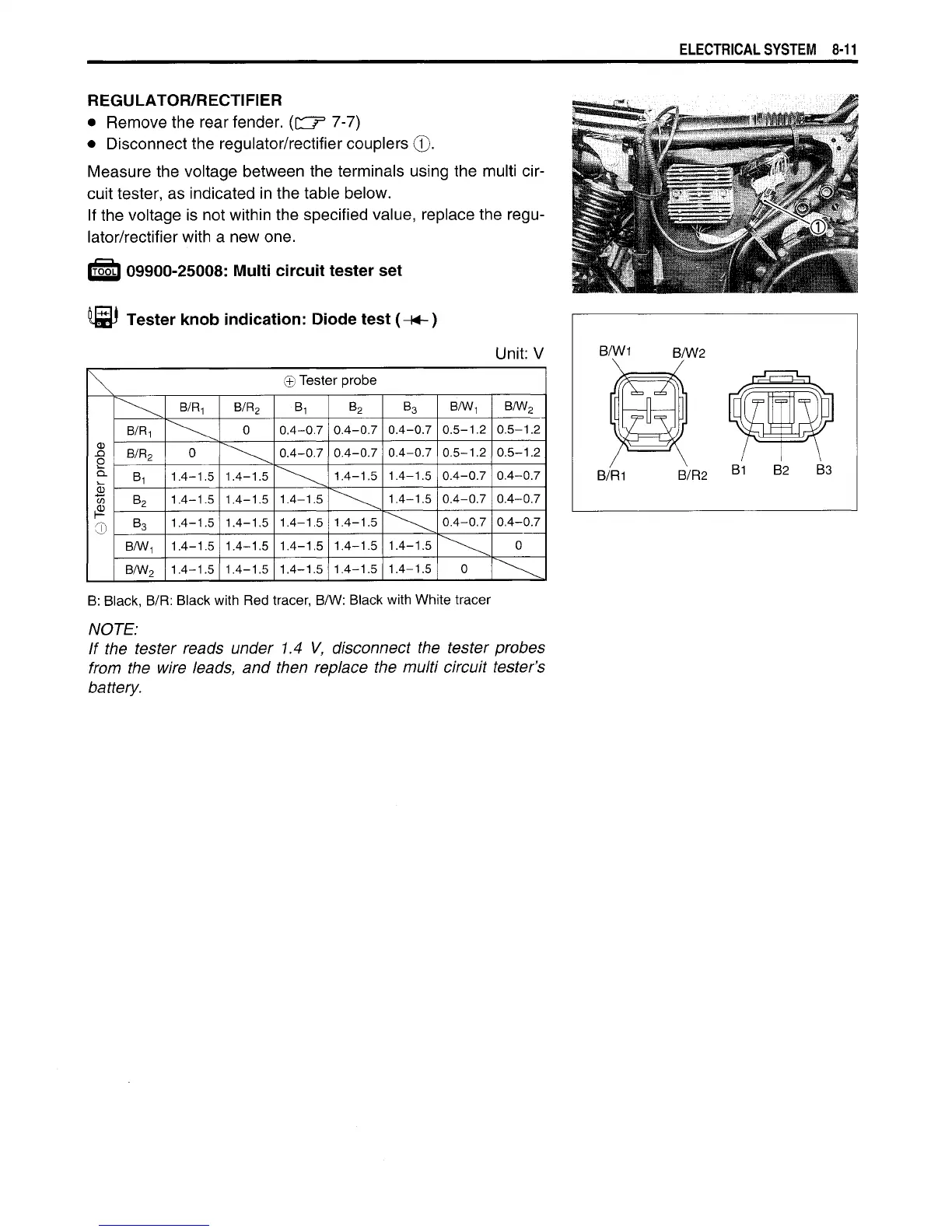
REGULATOR/RECTIFIER
•
Remove
the rear fender.
({OT 7-7)
•
Disconnect the
regulator/rectifier
couplers
©.
Measure the voltage between the terminals using the multi
cir-
cuit
tester,
as
indicated in the table below.
If
the voltage
is
not
within
the specified value, replace the regu-
lator/rectifier
with
a
new one.
IT55LI
09900-25008:
Multi
circuit tester set
Tester
knob indication: Diode test (H4-)
Unit:
V
\ ©
Tester probe
B/R-, B/R
2
B
1
B
2
B
3
B/W
1
B/W
2
B/R
1
0
0.4-0.7
0.4-0.7
0.4-0.7
0.5-1.2 0.5-1.2
obe
B/R
2
0
0.4-0.7
0.4-0.7
0.4-0.7 0.5-1.2 0.5-1.2
^_
CL
S*_
Bi
1.4-1.5
1.4-1.5
1.4-1.5
1.4-1.5
0.4-0.7 0.4-0.7
CD
GO
CD
B
2
1.4-1.5 1.4-1.5
1.4-1.5
1.4-1.5
0.4-0.7 0.4-0.7
F
©
B
3
1.4-1.5
1.4-1.5
1.4-1.5
1.4-1.5
0.4-0.7 0.4-0.7
F
©
B/W
1
1.4-1.5
1.4-1.5 1.4-1.5
1.4-1.5
1.4-1.5
0
B/W
2
1.4-1.5
1.4-1.5 1.4-1.5
1.4-1.5
1.4-1.5
0
B: Black,
B/R:
Black
with
Red
tracer,
B/W:
Black
with
White
tracer
NOTE:
If the tester reads under 1.4 V, disconnect the tester probes
from the wire leads, and then replace the
multi
circuit
tester's
battery.

 Loading...


