ENGINE
3-25
•
Compress
the
valve springs
and
remove
the
valve
cotters
from the valve stem using the special
tools.
(T||]
09916-14510:
Valve spring compressor
09916-14910:
Attachment
09916-84511:
Tweezers
Remove
the valve spring retainer and valve springs.
Remove
the valve from the other side.
•
Remove
the oil seal
with
long-nose pliers.
•
Remove
the valve spring seat.
NOTE:
Removal
of valves completes ordinary disassembling work. If
valve guides have to be removed for replacement after inspect-
ing the related parts, carry out the
steps
shown in the valve
guide servicing.
CYLINDER
HEAD DISTORTION
Decarbonize the combustion chamber.
Check
the
gasket surface
of the
cylinder head
for
distortion
using
a
straightedge
and
thickness gauge. Take clearance
readings
at
several places.
If any
clearance reading exceeds
the
service
limit,
replace the cylinder head
with
a
new one.
(^)
09900-20803:
Thickness gauge
mm Cylinder head distortion
Service
Limit: 0.05 mm
(0.002
in)
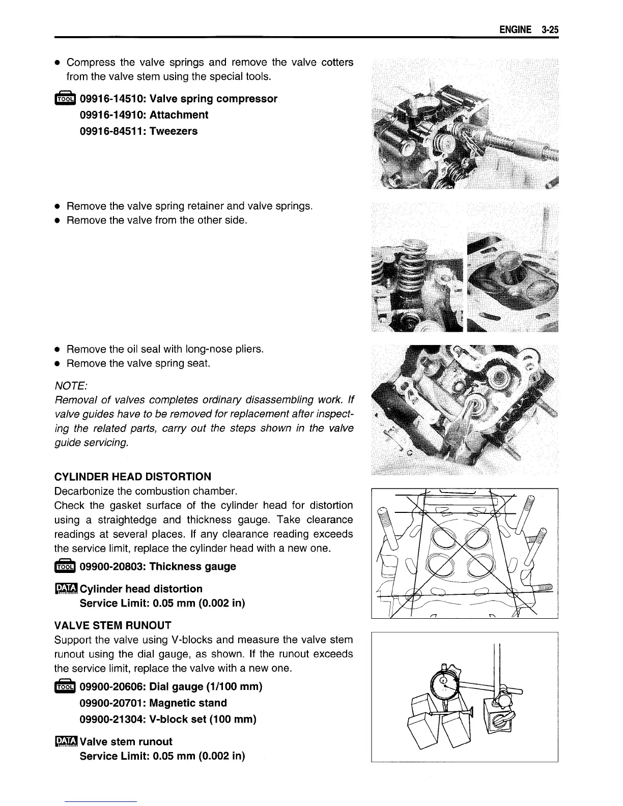
VALVE
STEM RUNOUT
Support the valve using V-blocks and measure the valve stem
runout using the dial gauge,
as
shown.
If
the runout exceeds
the
service
limit,
replace the valve
with
a
new one.
(T|5L]
09900-20606:
Dial gauge
(1/100
mm)
09900-20701:
Magnetic
stand
09900-21304:
V-block set (100 mm)
i^aq
Valve stem runout
Service
Limit: 0.05 mm
(0.002
in)

 Loading...


