ENGINE 3-75
CAMSHAFT/AUTOMATIC
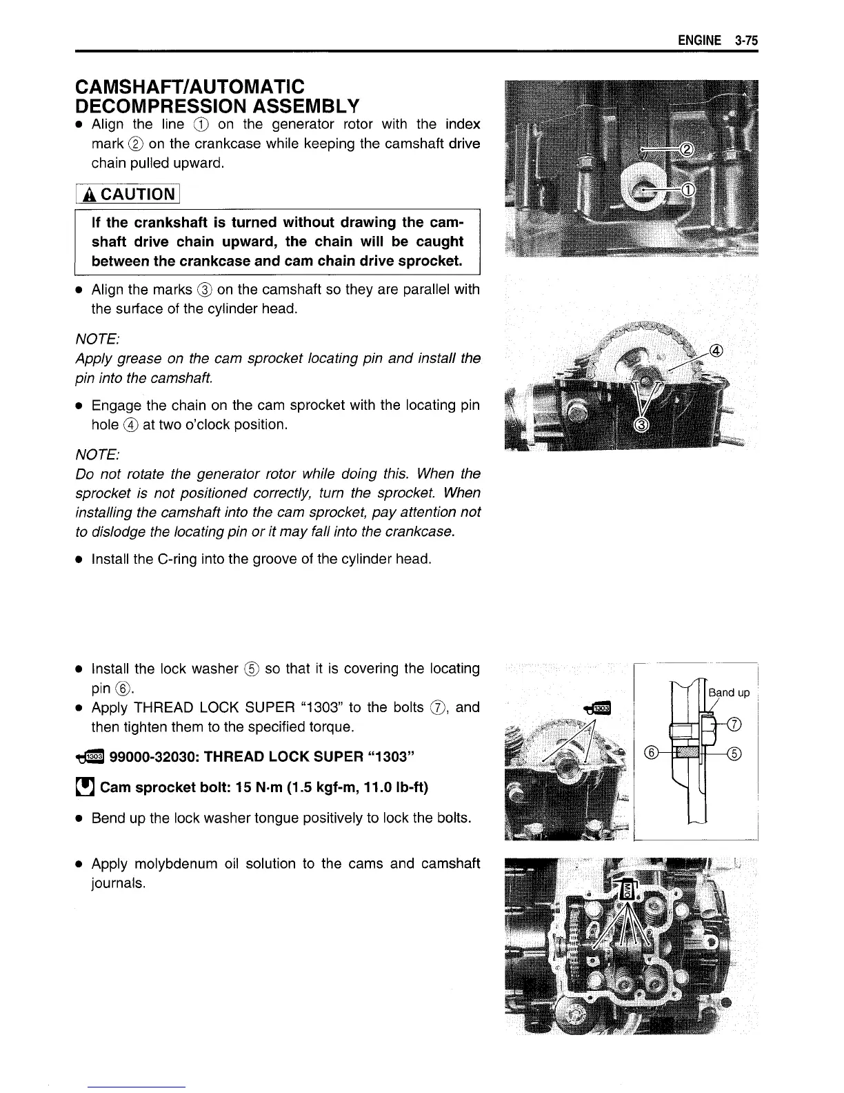
DECOMPRESSION ASSEMBLY
•
Align
the
line
© on the
generator rotor
with
the
index
mark
© on
the crankcase while keeping the camshaft drive
chain pulled upward.
A CAUTION
If the crankshaft is turned
without
drawing the cam-
shaft drive chain upward, the chain
will
be caught
between the crankcase and cam chain drive sprocket.
•
Align the marks
® on
the camshaft so they are parallel
with
the
surface of the cylinder head.
NOTE:
Apply grease on the cam sprocket locating pin and install the
pin
into
the camshaft.
•
Engage
the chain
on
the cam sprocket
with
the locating
pin
hole
@
at two o'clock position.
NOTE:
Do
not rotate the generator rotor while doing this. When the
sprocket
is not positioned correctly,
turn
the sprocket. When
installing the camshaft
into
the cam sprocket, pay attention not
to dislodge the locating pin or it may
fall
into
the crankcase.
Install
the
C-ring
into the groove of the cylinder head.
•
Install the lock washer
© so
that
it is
covering the locating
pin®.
•
Apply
THREAD
LOCK
SUPER
"1303"
to
the bolts
®, and
then tighten them to the specified torque.
t«3
99000-32030:
THREAD
LOCK
SUPER
"1303"
H Cam sprocket
bolt:
15 N m (1.5 kgf-m, 11.0
Ib-ft)
•
Bend
up the lock washer tongue positively to lock the bolts.
•
Apply
molybdenum
oil
solution
to the
cams
and
camshaft
journals.

 Loading...


