3-2 ENGINE
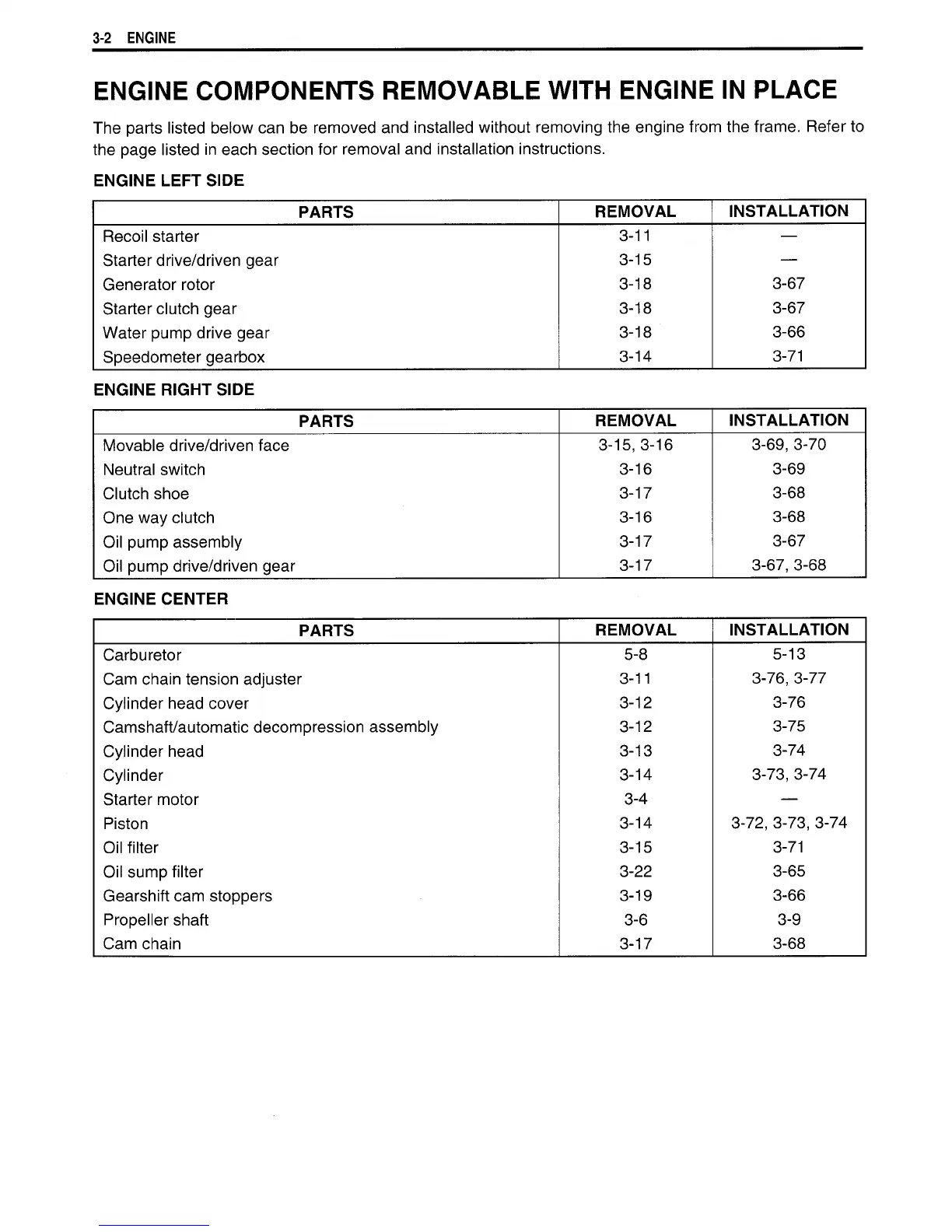
ENGINE
COMPONENTS
REMOVABLE
WITH
ENGINE IN
PLACE
The parts listed below can
be
removed and installed without removing the engine from the frame. Refer to
the
page listed in each section for removal and installation instructions.
ENGINE
LEFT
SIDE
PARTS
REMOVAL
INSTALLATION
Recoil starter
3-11
—
Starter
drive/driven gear
3-15
—
Generator rotor
3-18
3-67
Starter
clutch gear
3-18
3-67
Water pump drive gear
3-18 3-66
Speedometer gearbox 3-14 3-71
ENGINE
RIGHT
SIDE
PARTS
REMOVAL
INSTALLATION
Movable drive/driven face
3-15, 3-16
3-69, 3-70
Neutral switch
3-16
3-69
Clutch shoe
3-17
3-68
One way clutch
3-16
3-68
Oil pump assembly
3-17 3-67
Oil pump drive/driven gear 3-17 3-67, 3-68
ENGINE CENTER
PARTS
REMOVAL
INSTALLATION
Carburetor
5-8
5-13
Cam chain tension adjuster
3-11
3-76,
3-77
Cylinder head cover
3-12 3-76
Camshaft/automatic decompression assembly 3-12 3-75
Cylinder head
3-13 3-74
Cylinder
3-14 3-73, 3-74
Starter
motor 3-4
—
Piston
3-14
3-72, 3-73, 3-74
Oil
filter
3-15
3-71
Oil sump
filter
3-22
3-65
Gearshift cam stoppers 3-19 3-66
Propeller shaft 3-6 3-9
Cam chain 3-17 3-68

 Loading...


