ELECTRICAL
SYSTEM
8-21
IGNITION
COIL
RESISTANCE
•
Remove
the fuel tank. (dr* 5-2 and 5-3)
•
Disconnect the ignition coil lead wire, coupler,
and
remove
the
ignition
coil.
Measure
the
ignition coil resistance
in
both
the
primary
and
secondary windings using the multi circuit tester.
If
the resis-
tance
in
both the primary and secondary windings
is
close
to
the
specified values, the windings are in sound condition.
ITSSLI
09900-25008:
Multi
circuit tester set
Tester
knob indication:
Resistance
(1
>)
Ignition
coil resistance
Primary:
0.1-0.8
Q (© tap-© tap)
Secondary:
10-15
kQ (spark plug
cap-0
tap)
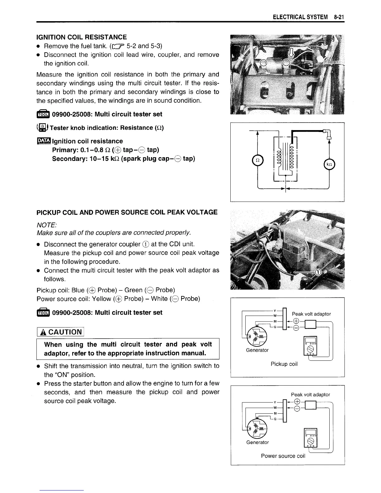
PICKUP
COIL AND POWER
SOURCE
COIL
PEAK
VOLTAGE
NOTE:
Make
sure
all of the couplers are connected properly.
•
Disconnect the generator coupler
©
at the CDI unit.
Measure the pickup coil and power source coil peak voltage
in
the following procedure.
•
Connect the multi circuit tester with the peak volt adaptor
as
follows.
Pickup
coil:
Blue
(©
Probe)
-
Green
(©
Probe)
Power source
coil:
Yellow
(©
Probe)
-
White
(©
Probe)
IT55LI 09900-25008:
Multi
circuit tester set
A CAUTION
When using the
multi
circuit tester and peak volt
adaptor, refer to the appropriate instruction manual.
•
Shift the transmission into neutral, turn the ignition switch
to
the
"ON" position.
•
Press the starter button and allow the engine to turn for a few
seconds,
and
then measure
the
pickup coil
and
power
source coil peak voltage.
w
Peak volt adaptor
Bl
_ ^©-p
Generator
Pickup coil
Peak volt adaptor
h-e-r
Generator
Power source coil

 Loading...


