8-10
ELECTRICAL
SYSTEM
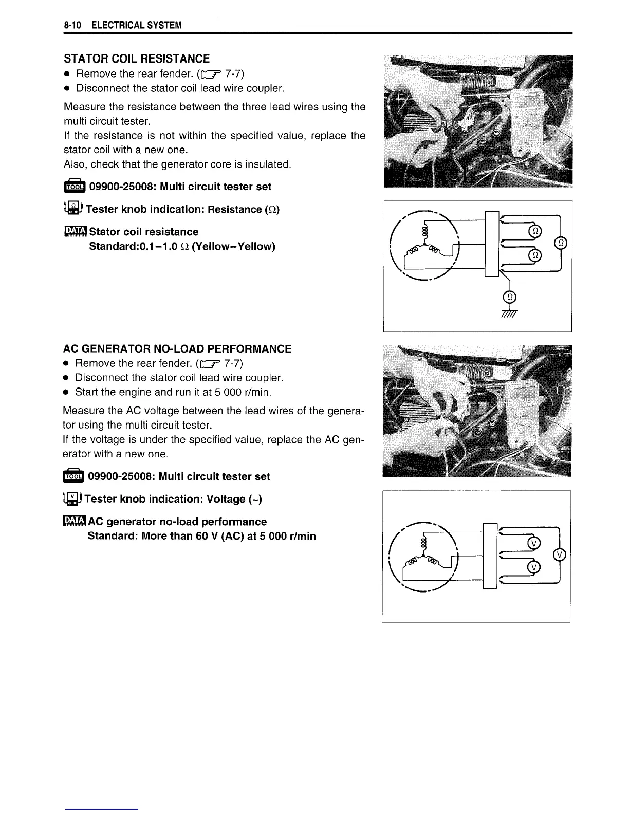
STATOR
COIL
RESISTANCE
•
Remove
the rear fender,
(dr
3
7-7)
• Disconnect the stator
coil
lead wire coupler.
Measure
the resistance between the three lead wires using the
multi
circuit
tester.
If
the resistance
is
not within the specified value, replace the
stator
coil
with
a
new one.
Also, check that the generator core is insulated.
IT55LI
09900-25008:
Multi
circuit tester set
Tester
knob indication:
Resistance
(Q)
Stator coil resistance
Standard:0.1-1.0 Q (Yellow-Yellow)
AC
GENERATOR
NO-LOAD PERFORMANCE
•
Remove
the rear fender.
({^J
=>
7-7)
• Disconnect the stator
coil
lead wire coupler.
• Start the engine and run it at
5
000 r/min.
Measure
the
AC
voltage between the lead wires
of
the genera-
tor
using the multi
circuit
tester.
If
the voltage
is
under the specified value, replace the
AC
gen-
erator
with
a
new one.
trSoi)
09900-25008:
Multi
circuit tester set
I Tester knob indication: Voltage (~)
ESSJ
AC generator no-load performance
Standard:
More
than 60 V (AC) at 5 000
r/min

 Loading...


