8-18
ELECTRICAL
SYSTEM
IGNITION
SYSTEM
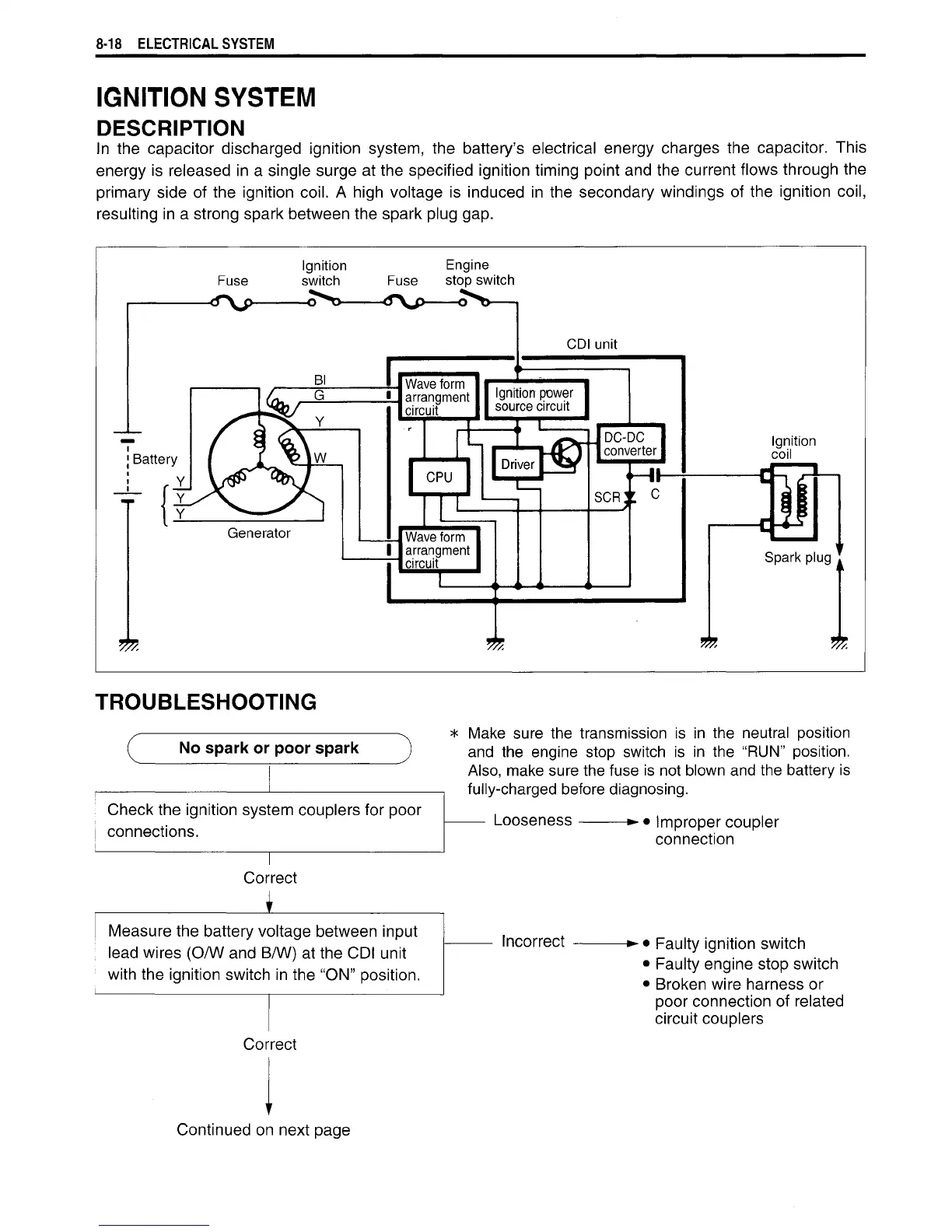
DESCRIPTION
In
the
capacitor discharged ignition system,
the
battery's electrical energy charges
the
capacitor. This
energy
is
released
in a
single surge at the specified ignition timing point and the current flows through the
primary side
of
the ignition
coil.
A
high voltage
is
induced
in the
secondary windings
of
the ignition
coil,
resulting
in
a
strong spark between the spark plug gap.
Ignition
Engine
Fuse
switch
Fuse
stop switch
Generator
Wave
form
arrangment
circuit
CDI unit
Ignition
power
source
circuit
CPU
Wave
form
arrangment
circuit
Ignition
coil
TROUBLESHOOTING
No spark or
poor
spark
Check the ignition sysl
connections.
em couplers for poor
1
Correct
\
Measure
the battery v<
lead wires
(O/W
and
E
with
the ignition switch
Dltage between input
>/W) at the
CDI
unit
in
the "ON" position.
Make
sure
the
transmission
is in the
neutral position
and
the
engine stop switch
is in the "RUN"
position.
Also, make sure the fuse
is
not blown and the battery
is
fully-charged before diagnosing.
Looseness
-• •
Improper coupler
connection
Incorrect
Faulty ignition switch
•
Faulty engine stop switch
•
Broken wire harness
or
poor connection
of
related
circuit
couplers
Correct
t
Continued
on
next
page

 Loading...


