4-36 SHAFT DRIVE AND
DIFFERENTIAL
BACKLASH
•
Install the final drive bevel gear, gear stopper and final drive
gear nut.
{{^T
4-39)
NOTE:
At this time, it is not necessary to install the
O-ring.
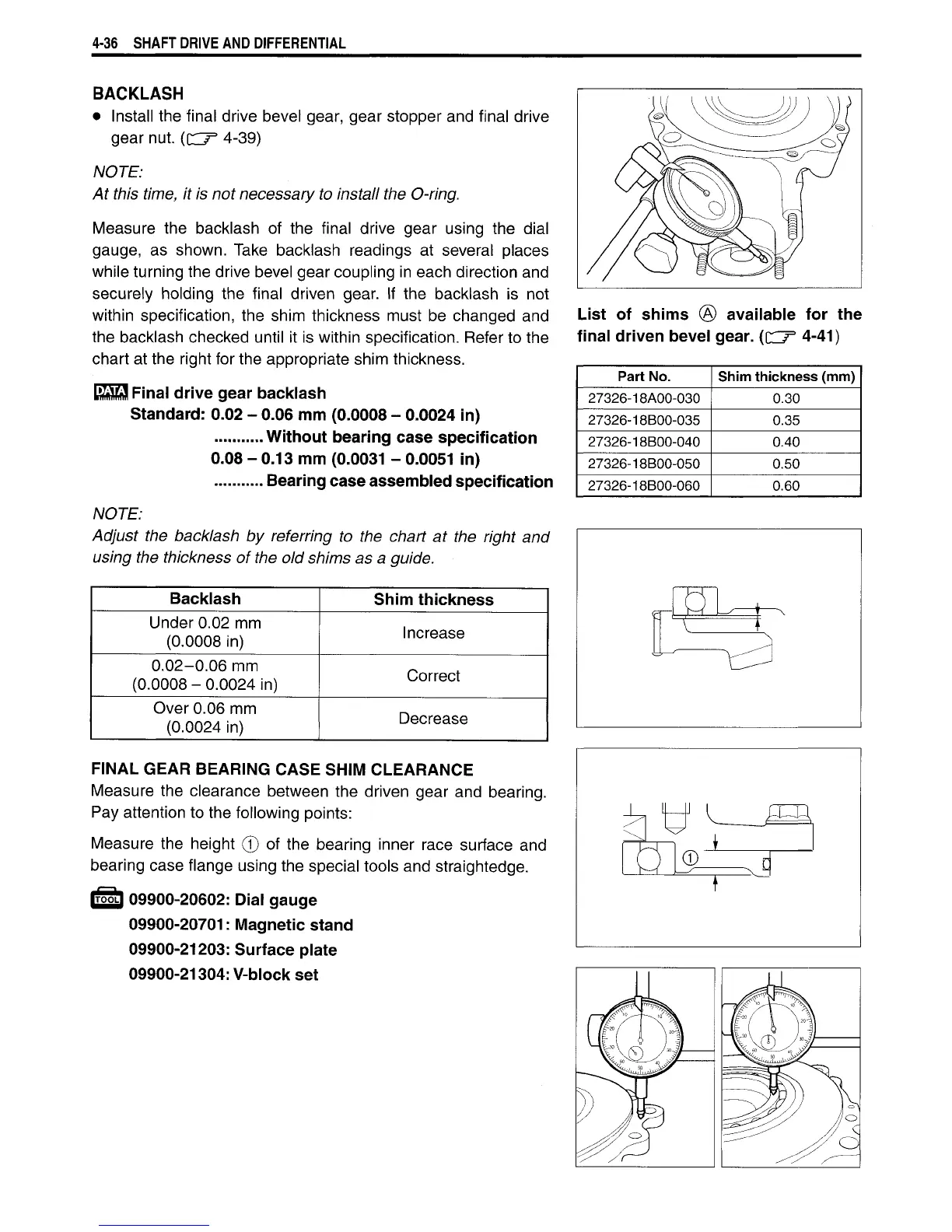
Measure
the
backlash
of the
final drive gear using
the
dial
gauge,
as
shown. Take backlash readings
at
several places
while
turning the drive bevel gear coupling in each direction and
securely holding
the
final driven gear.
If the
backlash
is not
within
specification,
the
shim thickness must
be
changed
and
the
backlash checked
until
it is
within
specification. Refer to the
chart
at the right for the appropriate shim thickness.
Final drive gear backlash
Standard: 0.02 - 0.06 mm
(0.0008
-
0.0024
in)
Without
bearing
case
specification
0.08 - 0.13 mm
(0.0031
-
0.0051
in)
Bearing
case
assembled specification
NOTE:
Adjust the backlash by referring to the chart at the
right
and
using
the thickness of the old shims as a guide.
Backlash
Shim thickness
Under 0.02 mm
(0.0008
in)
Increase
0.02-0.06
mm
(0.0008
-
0.0024
in)
Correct
Over
0.06 mm
(0.0024
in)
Decrease
FINAL
GEAR
BEARING
CASE
SHIM
CLEARANCE
Measure
the clearance between the driven gear and bearing.
Pay attention to the following points:
Measure
the height
0 of
the bearing inner race surface
and
bearing case flange using the special tools and straightedge.
IT55LI
09900-20602:
Dial gauge
09900-20701:
Magnetic
stand
09900-21203:
Surface
plate
09900-21304:
V-block set
List
of shims ® available for the
final
driven bevel gear. (CC7
3
4-41)
Part No.
Shim
thickness (mm)
27326-18A00-030
0.30
27326-18B00-035 0.35
27326-18B00-040 0.40
27326-18B00-050 0.50
27326-18B00-060 0.60

 Loading...


