EasyManuals Logo
Home>Xerox>Printer>Phaser 7100

Xerox Phaser 7100 Service Manual

Xerox Phaser 7100
1146 pages
To Next Page IconTo Next Page
To Previous Page IconTo Previous Page
Page #1082 background imageLoading...
Page #1082 background image
Plug/Jack and Wiring Diagrams
Phaser 7100 Service Manual Xerox Internal Use Only7-28
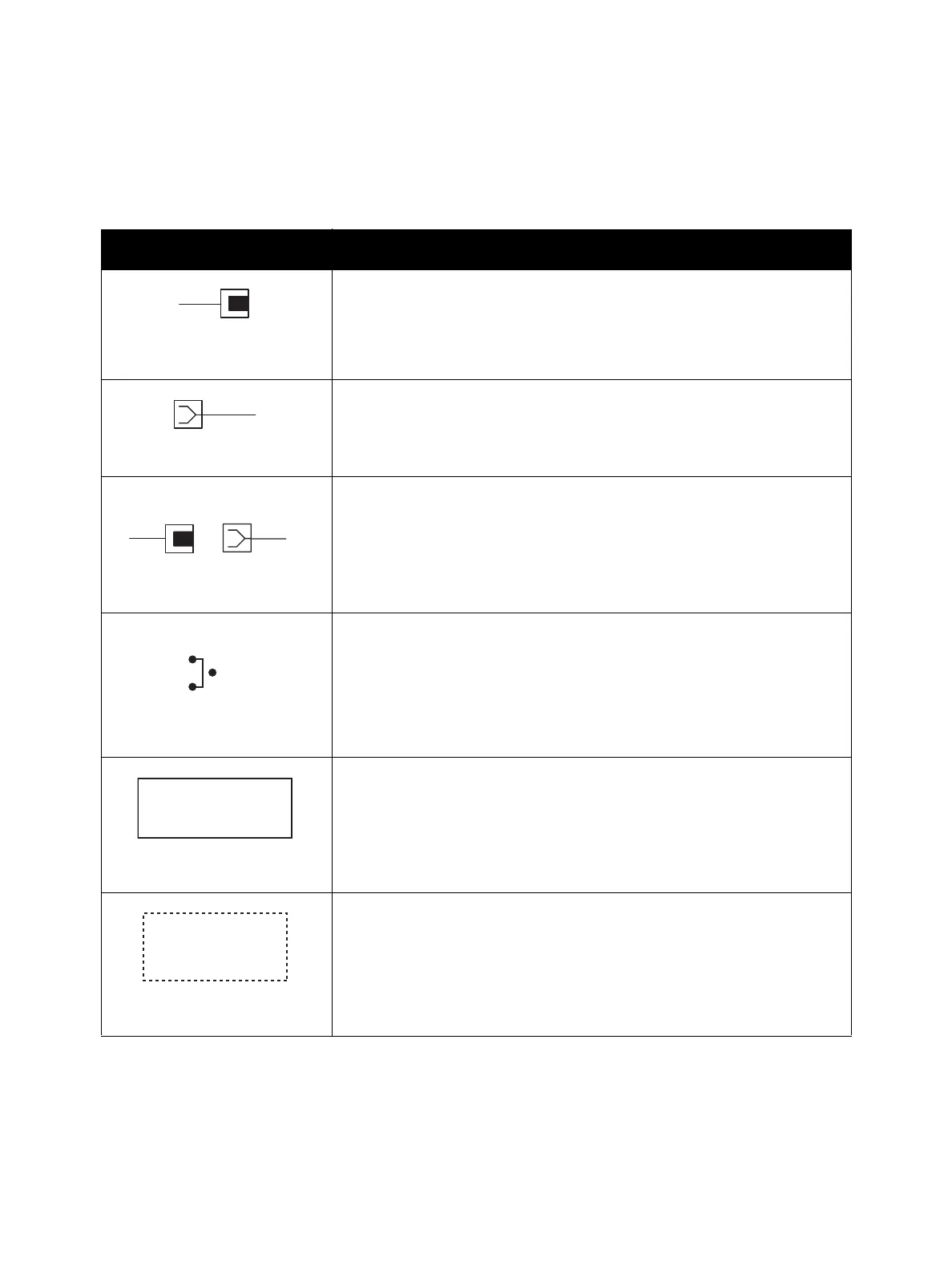
Notations Used in the Wiring Diagrams
The following table lists the symbols used in the wiring diagrams.
Symbol Description
Denotes a Plug.
Denotes a Jack.
Denotes Pin yy and Jack yy of the connector Pxx and Jxx.
Denotes a Jumper Point (JPxxx/xxx). Each end of the Jumper connection
has a numeric designation.
Denotes the parts.PL X.Y.Z implies the item “Z” of plate (PL) “X.Y” in Parts
List.
Denotes functional parts attached with functional parts name.
Plug
Jack
P/Jxx
YY
Plug and Jack
JPxxx
Jumper
Fuser
PL X.Y.Z
Subassembly 1
Heater
Subassembly 2

Table of Contents

Other manuals for Xerox Phaser 7100

Questions and Answers:

Question and Answer IconNeed help?

Do you have a question about the Xerox Phaser 7100 and is the answer not in the manual?

Xerox Phaser 7100 Specifications

General IconGeneral
BrandXerox
ModelPhaser 7100
CategoryPrinter
LanguageEnglish

Related product manuals