Plug/Jack and Wiring Diagrams
Xerox Internal Use Only Phaser 7100 Service Manual 7-35
Print Engine Wiring Diagrams
Wiring Diagram Organization
The Connection Charts are divided into 14 sections and shows the connection between the parts in
detail.
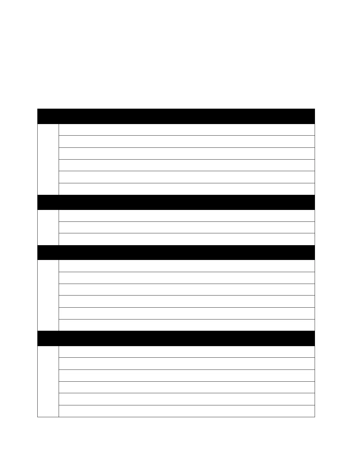
1 Power
Connection between the LVPS Fan Assembly and the LVPS PWB.
Check the conductivity between Front Cover Interlock Switch and the LVPS PWB.
Check the conductivity between Waste Cartridge Set Switch and the LVPS PWB.
Check the conductivity between Toner Cover Interlock Switch and the LVPS PWB.
Connection between the AC PWB and the LVPS PWB.
Connection between the MCU PWB and the LVPS PWB.
2 Fusing Unit
Connection between the Fuser Unit and the MCU PWB.
Connection between the AC PWB and the MCU PWB.
Connection between the Fuser Unit and the AC PWB.
3 Drive 1
Connection between the Drum Motor (Y/ M/ C) and the MCU PWB.
Connection between the Drum Motor (Y/ M/ C) and the LVPS PWB.
Connection between the Drum Motor (K) and the MCU PWB.
Connection between the Drum Motor (K) and the LVPS PWB.
Connection between the Paper Handling Motor and the MCU PWB.
Connection between the Paper Handling Motor (Y/ M/ C) and the LVPS PWB.
4 Drive 2/ Bypass Tray
Connection between the Deve Motor PWB Assembly and the MCU PWB.
Connection between the Deve Motor PWB Assembly and the LVPS PWB.
Connection between the Fuser Unit Motor and the MCU PWB.
Connection between the Fuser Unit Motor and the LVPS PWB.
Connection between the Bypass Tray No Paper Sensor and the MCU PWB.
Connection between the Bypass Tray Feed Solenoid and the MCU PWB.
 Loading...


