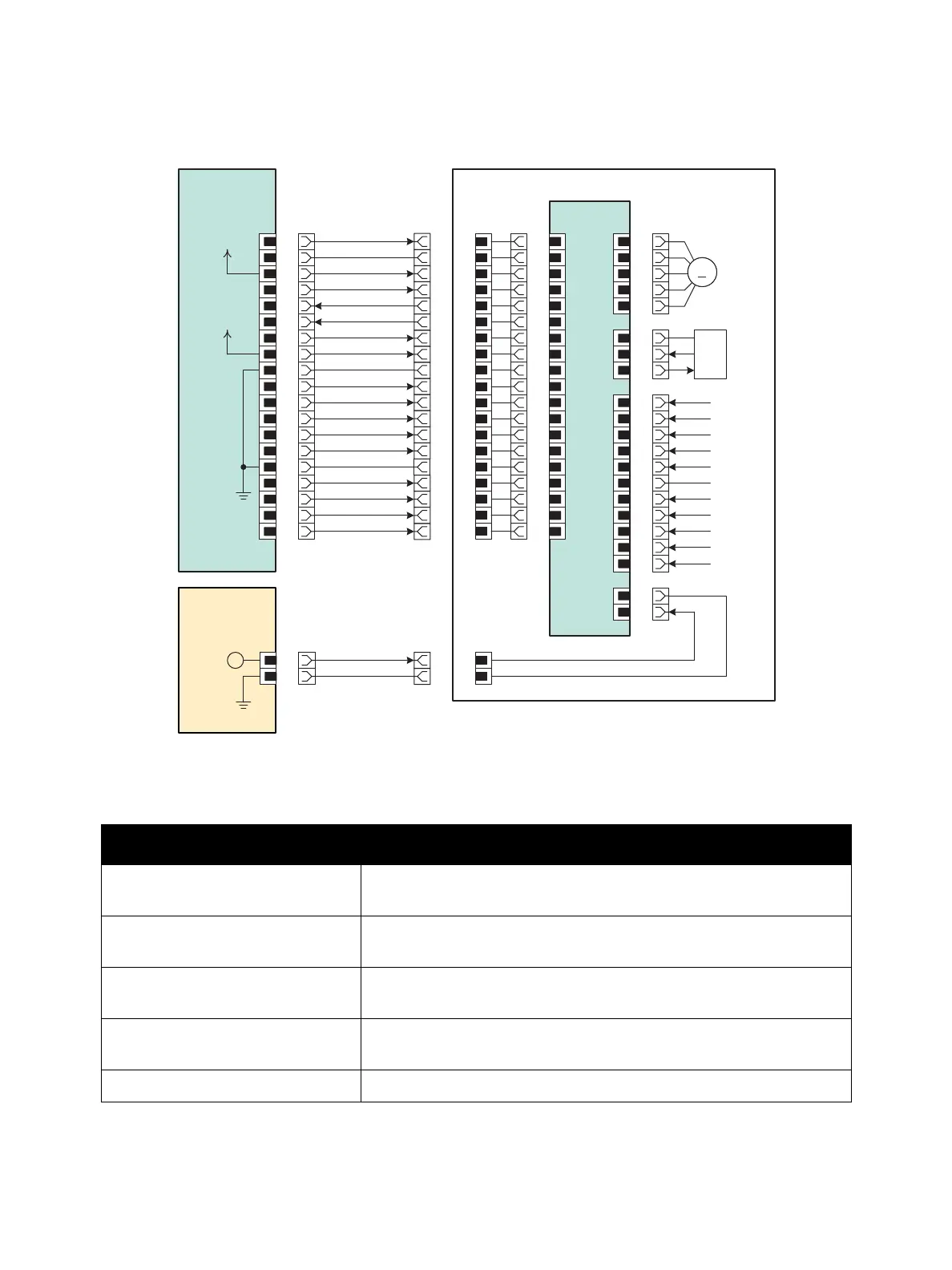
Plug/Jack and Wiring Diagrams
Xerox Internal Use Only Phaser 7100 Service Manual 7-47
Laser Unit (ROS)
ROS Signal Lines
Signal Line Name Description
Motor On The On/ Off Control signal of the Scanner Motor in the Laser Unit (ROS
Assembly)
Clock The Clock signal of the Scanner Motor in the Laser Unit (ROS
Assembly)
SOS Signal The Laser Beam Scan Start Reference signal detected by the SOS
Sensor in the Laser Unit (ROS Assembly)
LD Error The Error signal from the LD (Laser Diode) in the Laser Unit (ROS
Assembly)
PCONT The Control signal of the LD in the Laser Unit (ROS Assembly)
J5251
2
MCU PWB
P/J469
1
2
J4691
19
P4691 P/J401
1
218
SOS Signal
Clock
3
4
3
4
17
16
Motor On
5 515
6 614
7 713
SG
8 12 8
+3.3VDC
19
18
17
16
15
14
13
12
ROS PWB
LVPS PWB
P/J525
1
2
P5251
1
21
SG
LD 5V
P/J403
1
2
+3.3VDC
I/L +24VDC
9
10
11
12
13
14
15
16
17
18
19
ROS Assembly
911
10
11
10
9
128
137
146
5 15
11
10
9
8
7
6
5
164
173
182
191
4
3
2
1
P/J405
1
2
3
4
5
P/J404
1
2
3
P/J402
1
2
3
4
5
6
7
8
9
10
11
Scanner
Motor
SOS
Sensor
Rtn
I/L +24VDC
LD Error
PCONT
VREF K
VREF C
VREF M
VREF Y
LD ENB
SG
Pdata K
Pdata C
Pdata M
Pdata Y
From I/P PWB
B
From Power
M
s7100-305
 Loading...


