Zynq-7000 AP SoC and 7 Series FPGAs MIS v4.1 460
UG586 November 30, 2016
www.xilinx.com
Chapter 3: RLDRAM II and RLDRAM 3 Memory Interface Solutions
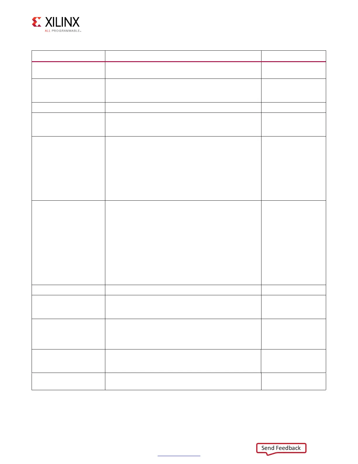
BUFMR_DELAY
Simulation-only parameter used to model buffer delays
(RLDRAM II only).
–
RST_ACT_LOW
Active-Low or active-High reset. This is set to 1 when
System Reset Polarity option is selected as active-Low and
set to 0 when the option is selected as active-High.
0, 1
IBUF_LPWR_MODE Enables or disables low power mode for the input buffers. ON, OFF
IODELAY_HP_MODE
Enables or disables high-performance mode within the
IODELAY primitive. When set to OFF, IODELAY operates in
low power mode at the expense of performance.
ON, OFF
SYSCLK_TYPE
This parameter indicates whether the system uses
single-ended system clocks, differential system clocks, or
is driven from an internal clock (No Buffer). Based on the
selected CLK_TYPE, the clocks must be placed on the
correct input ports. For differential clocks,
sys_clk_p/sys_clk_n must be used. For single-ended clocks,
sys_clk_i must be used. For the No Buffer option, sys_clk_i,
which appears in the port list, needs to be driven from an
internal clock.
DIFFERENTIAL,
SINGLE_ENDED,
NO_BUFFER
REFCLK_TYPE
This parameter indicates whether the system uses
single-ended reference clocks, differential reference
clocks, is driven from an internal clock (No Buffer), or can
connect to the system clock input only (Use System Clock).
Based on the selected CLK_TYPE, the clocks must be placed
on the correct input ports. For differential clocks,
clk_ref_p/clk_ref_n must be used. For single-ended clocks,
clk_ref_i must be used. For the No Buffer option, clk_ref_i,
which appears in the port list, needs to be driven from an
internal clock. For the Use System Clock option, clk_ref_i is
connected to the system clock in the user design top
module.
DIFFERENTIAL,
SINGLE_ENDED,
NO_BUFFER,
USE_SYSTEM_CLOCK
CLKIN_PERIOD Input clock period. –
CLKFBOUT_MULT
PLL voltage-controlled oscillator (VCO) multiplier. This
value is set by the MIG tool based on the frequency of
operation.
–
CLKOUT0_DIVIDE,
CLKOUT1_DIVIDE,
CLKOUT2_DIVIDE,
CLKOUT3_DIVIDE
VCO output divisor for PLL outputs. This value is set by the
MIG tool based on the frequency of operation.
–
CLKOUT0_PHASE
Phase of PLL output CLKOUT0. This value is set by the MIG
based on the banks selected for memory interface pins and
the frequency of operation.
–
DIVCLK_DIVIDE
PLL VCO divisor. This value is set by the MIG tool based on
the frequency of operation.
–
Table 3-14: RLDRAM II Memory Interface Solution Configurable Parameters (Cont’d)
Parameter Description Options
 Loading...


